


Basic Operation
3–2
AlphaServer Intelligent Peripheral Platform Hardware Owner's Guide
3.3
Basic Operation of the IP Platform Subsystem Components
The following sections describe the basic operation of the IP Platform subsystem components.
3.3.1
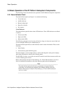
Alarm Indicator Panel
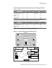
The alarm indicator panel (see Figure 3-1) contains the following:
•
Visual indicators
•
Audible indicator
•
Battery backup logic
•
Keep-alive function
•
Dry contacts
Visual Indicators
The alarm indicator panel has three alarm LED indicators. These LED indicators are defined
as follows:
•
Critical (red LED)
•
Major (red LED)
•
Minor (amber LED)
The LED for a particular level of severity will be lit as long as at least one event of that level
is active. Multiple LEDs may be simultaneously lit.
The alarm indicator panel has two other indicators used for status information. These are the
following:
•
Status display
•
Alarm indicator panel OK LED (green)
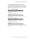
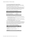
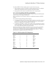
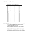
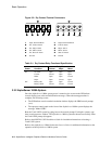
The status display is used to output status as a result of the diagnostic testing and to display
other status information as shown in the following tables.
The OK LED is lit after a successful reset and will remain lit until either an unsuccessful reset
or a loss of battery power occurs.
Refer to the Intelligent Peripheral Fault Manager For Tru64 UNIX Installation and User's
Guide for additional information on the alarm indicator panel and fault management.
______________________________ Note ___________________________
The alarm indicator panel should not be permanently removed without de-
configuring it in the Intelligent peripheral Fault Manager (IPFM) config file.
Refer to the Intelligent Peripheral Fault Manager for Tru64 UNIX Installation
and User's Guide.
______________________________________________________________