


AlphaServer Intelligent Peripheral Platform Hardware Owner's Guide B–1
B
Alarm Input Wiring
B.1
Alarm Input Wiring Diagram
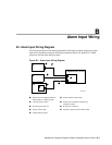
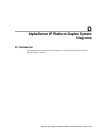
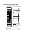
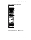
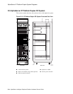
The following diagram of the Intelligent Peripheral (IP) duplex platform displays the alarm
input wiring connections between the ISA bus expansion chassis, the AlphaServer 1000A
processors, and the alarm indicator panel.
Figure B-1: Alarm Input Wiring Diagram
AlphaServer 1000A
1
2
5
7
ISA
3
4
6
8
9
ML014035
➊
Alarm control module installed in
the
AlphaServer
1000A system
➏
Alarm indicator panel cable
➋
-48 Vdc power inverter
➐
Alarm sensor module in the ISA bus
expansion chassis
➌
D-sub 25-pin connector
➑
D-sub 9-pin connector
➍
Inverter alarm cable
➒
ISA bus expansion chassis alarm cable
➎
Alarm indicator panel