Alarm Input Wiring
B–2
AlphaServer Intelligent Peripheral Platform Hardware Owner's Guide
B.2
Wiring User Alarm Inputs
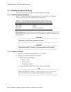
This section provides information for wiring user TTL signal alarm inputs to the 8-pin MJ
connector on the alarm control module installed in the AlphaServer 1000A system.
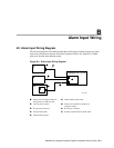
Figure B-2 shows the 8-pin MJ connector on the alarm control module that is used for
connecting user alarm inputs.
Figure B-2: Alarm Control Module 8-Pin MJ Connector
1
8
ML014036
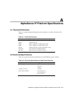
Table B–1 provides a pinout listing of the pins on the alarm control module 8-pin MJ
connector. This table should be used to determine the correct wiring required for user alarm
inputs.
Table B–1: Alarm Control Module 8-Pin MJ Connector Pinout
Pin No. Signal
1 Inverter Fail or user input 1 Return
2 Inverter Fail or user input 1
3 Inverter Minor or user input 2 Return
4 Inverter Minor or user input 2
5 Inverter Major or user input 3 Return
6 Inverter Major or user input 3
7 Not used
8 Not used


