


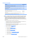
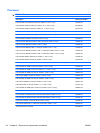
Fan/heat sink assembly
Description Spare part number
Fan/heat sink assembly for use in models that use Universal Memory Architecture (UMA) graphics
subsystem memory (includes thermal replacement material)
595832-001
Fan/heat sink assembly for use in models that use discrete graphics subsystem memory (includes
thermal replacement material)
595833-001
Fan/heat sink assembly for use in models that use HD545V discrete graphics subsystem memory
(for model 1.1 only)
617024-001
Fan/heat sink assembly for use in models that use GL40 Universal Memory Architecture (UMA)
graphics subsystem memory (includes thermal replacement material)
606573-001
Thermal pad kit for South Bridge chipset 634433-001
Fan/heat sink assembly for use in models that use discrete graphics subsystem memory (for
model 1.3 only)
634650-001
Fan/heat sink assembly for use in models that use Universal Memory Architecture (UMA) graphics
subsystem memory (includes thermal replacement material) (for model 1.3 only)
634651-001
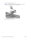
NOTE: To properly ventilate the computer, allow at least a 7.6-cm (3-inch) clearance on the right
side and rear panel of the computer. The computer uses an electric fan for ventilation. The fan is
controlled by a temperature sensor and is designed to turn on automatically when high temperature
conditions exist. These conditions are affected by high external temperatures, system power
consumption, power management/battery conservation configurations, battery fast charging, and
software requirements. Exhaust air is displaced through the ventilation grill located on the left side of
the computer.
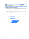
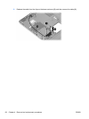
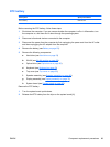
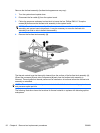
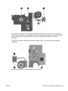
Before removing the fan/heat sink assembly, follow these steps:
1. Shut down the computer. If you are unsure whether the computer is off or in Hibernation, turn
the computer on, and then shut it down through the operating system.
2. Disconnect all external devices connected to the computer.
3. Disconnect the power from the computer by first unplugging the power cord from the AC outlet
and then unplugging the AC adapter from the computer.
4. Remove the battery (see
Battery on page 52).
5. Remove the following components:
a. Hard drive (see
Hard drive on page 53)
b. Optical drive (see
Optical drive on page 56)
c. Keyboard (see
Keyboard on page 63)
d. Top cover (see
Top cover on page 65)
e. Speaker assembly (see
Speaker assembly on page 68)
f. Display assembly (see
Display assembly on page 76)
g. System board (see
System board on page 83)
ENWW Component replacement procedures 91