


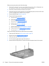

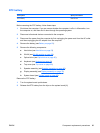
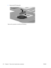
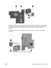
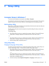
Remove the fan/heat assembly (fan/heat sink appearance may vary):
1. Turn the system board upside down.
2. Disconnect the fan cable (1) from the system board.
3. Follow the sequence embossed on heat sink to loosen the four Phillips PM2.5×7.0 captive
screws (2) that secure the fan/heat sink assembly to the system board.
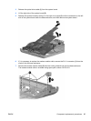
NOTE: Due to the adhesive quality of the thermal material located between the fan/heat sink
assembly and system board components, it may be necessary to move the fan/heat sink
assembly from side to side to detach the assembly.
4. Remove the fan/heat sink assembly (3).
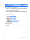
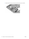
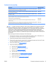
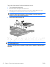
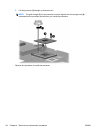
The thermal material must be thoroughly cleaned from the surface of the fan/heat sink assembly (1),
(3) and the processor (2) and video components (4) each time the fan/heat sink assembly is
removed. Thermal pads and thermal paste must be installed on all surfaces before the fan/heat sink
assembly is reinstalled.
NOTE: Thermal pads and thermal paste are included with all fan/heat sink assembly, system board,
and processor spare part kits.
The following illustration shows the locations for thermal material on systems with discrete graphics
subsystems.
92 Chapter 4 Removal and replacement procedures ENWW