


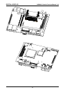

DIGITAL-LOGIC AG MSB900/L Detailed Technical Manual V1.0
28
5.6. Timers and Counters
5.6.1. Programmable Timers
An 8253 compatible timer/counter device is also included in the board's ASIC device. This device is utilized
in precisely the same manner as in a standard AT implementation. Each channel of the 8253 is driven by a
1.190 MHz clock, derived from a 14.318 MHz oscillator, which can be internally divided in order to provide a
variety of frequencies.
Timer 2 can also be used as a general purpose timer if the speaker function is not required.
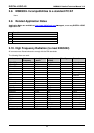
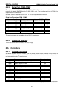
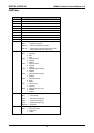
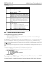
Timer Assignment
Timer Function
0 ROM-BIOS clock tick (18.2Hz)
1 DRAM refresh request timing (15 µs)
2 Speaker tone generation time base
5.6.2. RTC (Real Time Clock)
An AT compatible date/time clock is located within the chipset. The device also contains a CMOS static
RAM, compatible with that in standard ATs. System configuration data is normally stored in the clock chip's
CMOS RAM in a manner consistent with the convention used in other AT compatible computers. To attach
an external battery on a MSB900L board refer to section 2.11.1.
5.6.3. Watchdog
The watchdog timer detects a system crash and performs a hardware reset. After power up, the watchdog is
always disabled as the BIOS does not send strobes to the watchdog. In case the user wants to take advan-
tage of the watchdog, the application must produce a strobe at least every 800 ms. If no strobe occurs within
the 800 ms, the watchdog resets the system.
For more information, please refer to the driver/software/BIOS manual “GEODE_LX800-LX900” on the Prod-
uct CD. The watchdog feature is integrated in the INT15 function.
There are some programming examples available:
Product CD-Rom or customer download area: \tools\SM855\int15dl\…
5.6.4. ROM-BIOS Sockets
An EPROM socket with 8bit wide data access normally contains the board’s AT compatible ROM-BIOS. The
socket takes a 29F020 EPROM (or equivalent) device. The board's wait-state control logic automatically in-
serts four memory wait states in all CPU accesses to this socket. The ROM-BIOS sockets occupy the mem-
ory area from C0000H through FFFFFh; however, the board's ASIC logic reserves the entire area from
C0000h through FFFFFh for onboard devices, so that this area is already usable for ROM-DOS and BIOS
expansion modules. Consult the appropriate address map for the MICROSPACE PC-Product ROM-BIOS
sockets.