


DIGITAL-LOGIC AG MSB900/L Detailed Technical Manual V1.0
56
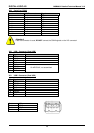
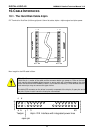
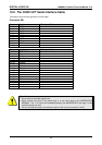
10.2. The COM1/LPT Serial Interface Cable
Terminal for dual row 2mm grid and 1mm flat cable.
Connector X61
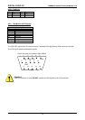
Pin Signal COM1 9pin D-Sub male
Pin 1 = DCD 1
Pin 2 = DSR 6
Pin 3 = RXD 2
Pin 4 = RTS 7
Pin 5 = TXD 3
Pin 6 = CTS 8
Pin 7 = DTR 4
Pin 8 = RI 9
Pin 9 = GND 5
Pin 10
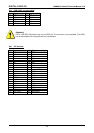
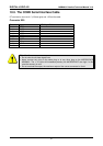
Pin Signal LPT1 25pin D-Sub female
Pin 11 = SELECT 13
Pin 12 = Paper end 12
Pin 13 = Busy 11
Pin 14 = Acknowledge 10
Pin 15 = Data 7 9
Pin 16 = Data 6 8
Pin 17 = Data 5 7
Pin 18 = Data 4 6
Pin 19 = Data 3 5
Pin 20 = Shift in 17
Pin 21 = Data 2 4
Pin 22 = Init 16
Pin 23 = Data 1 3
Pin 24 = Error 15
Pin 25 = Data 0 2
Pin 26 = Autofeed 14
Pin 27 = Strobe 1
Pin 28 = GND 18-25
Attention!
• Do not short circuit these signal lines.
• Never connect any pins on the same plug or to any other plug on the MICROSPACE
MSB900/L. The +/-10 Volts will immediately destroy the MICROSPACE core logic. In this
case the warranty is void!
• Do not overload the output; the maximum output of the current converters is 10mA.