


DIGITAL-LOGIC AG MSB900/L Detailed Technical Manual V1.0
53
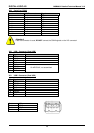
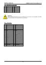
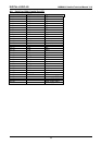
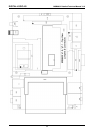
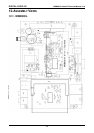
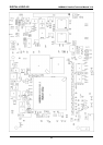
9. JUMPER LOCATIONS ON THE BOARD
The following figure shows the location of all jumper blocks on the MSB900/L board. The numbers shown in
this figure are silk screened on the board so that the pins can easily be located. This chapter refers to the
individual pins for these jumpers. The default jumper settings are indicated with asterisks.
Be careful: some jumpers are soldering bridges; you will need a miniature soldering station with a vacuum
pump.
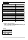
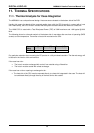
9.1. The Jumpers on MSB900/L
Settings written in bold are defaults.
Jumper Structure 1-2 / open 2-3 / closed
Remarks
J1 CompactFlash master Slave
Master
J2 Autostart function Enabled N/A
1)
J3 Disconnect Battery
Disabled
N/A
J4 Disconnect CMOS EEPROM
Disabled
N/A
1) With the autostart function enabled, the system will start booting up within 2 seconds after the power
supply is turned on.
9.2. Reload Default BIOS Settings
To reload default BIOS settings when the system refuses to boot after defective BIOS settings have been
made please proceed as follows.
• Turn off the system.
• Remove J3 on MSB900 or disconnect the optional external battery on the MSB900L.
• Remove J4.
• Turn on the system and enter the BIOS setup menu.
• Close J4 and J5 or attach the optional external battery.
• Choose save and exit in the BIOS setup menu.