


DIGITAL-LOGIC AG MSEBX800/900 Detailed Manual V1.0
29
4. BUS SIGNALS
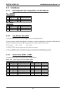
4.1. PC104 Bus
Note...
The ISA-Bus may have some minor incompatibilities, see Chapter 6.
AEN, output
Address Enable: used to degate the microprocessor and other devices from the I/O channel to allow
DMA transfers to take place. low = CPU Cycle, high = DMA Cycle
BALE, output
Address Latch Enable: provided by the bus controller and used on the system board to latch valid
addresses and memory decodes from the microprocessor. This signal is used so that devices on the
bus can latch LA17-23. The SA0-19 address lines latch internally according to this signal. BALE is
forced high during DMA cycles.
/DACK[0-3, 5-7], output
DMA Acknowledge: 0 to 3 and 5 to 7 are used to acknowledge DMA requests (DRQ0 through DRQ7).
They are active low. This signal indicates that the DMA operation can begin.
DRQ[0-3, 5-7], input
DMA Requests: 0 through 3 and 5 through 7 are asynchronous channel requests used by peripheral
devices and the I/O channel microprocessors to gain DMA service (or control of the system). A
request is generated by bringing a DRQ line to an active level. A DRQ line must be held high until the
corresponding DMA Request Acknowledge (DACK/) line goes active. DRQ0 through DRQ3 will
perform 8bit DMA transfers; DRQ5-7 are used for 16 accesses.
/IOCHCK, input
IOCHCK/: provides the system board with parity (error) information about memory or devices on the
I/O channel. low = parity error, high = normal operation
IOCHRDY, input
I/O Channel Ready: pulled low (not ready) by a memory or I/O device to lengthen I/O or memory
cycles. Any slow device using this line should drive it low immediately upon detecting its valid address
and a Read or Write command. Machine cycles are extended by an integral number of one clock cycle
(67 nanoseconds). This signal should be held in the range of 125-15600nS. low = wait, high =
normal operation
/IOCS16, input
I/O 16 Bit Chip Select: signals the system board that the present data transfer is a 16bit, 1 wait-state,
I/O cycle. It is derived from an address decode. /IOCS16 is active low and should be driven with an
open collector (300 Ohm pull-up) or tri-state driver capable of sinking 20mA. The signal is driven
based only on SA15-SAO (not /IOR or /IOW) when AEN is not asserted. In the 8bit I/O transfer, the
default transfers a 4 wait-state cycle.
/IOR, input/output
I/O Read: instructs an I/O device to drive its data onto the data bus. It may be driven by the system
microprocessor or DMA controller, or by a microprocessor or DMA controller resident on the I/O
channel. This signal is active low.
/IOW, input/output
I/O Write: instructs an I/O device to read the data on the data bus. It may be driven by any
microprocessor or DMA controller in the system. This signal is active low.
IRQ [3-7, 9-12, 14, 15], input
These signals are used to tell the microprocessor that an I/O device needs attention. An interrupt
request is generated when an IRQ line is raised from low to high. The line must be held high until
the microprocessor acknowledges the interrupt request.