


DIGITAL-LOGIC AG MSEBX800/900 Detailed Manual V1.0
31
/SMEMW, input/output
These signals instruct the memory devices to store the data present on the data bus for the first
MByte. /SMEMW is active in all memory read cycles. /SMEMW may be driven by any microprocessor
or DMA controller in the system. When a microprocessor on the I/O channel wishes to drive /SMEMW,
it must have the address lines valid on the bus for one system clock period before driving /SMEMW
active. Both signals are active low.
SYSCLK, output
This is an 8MHz system clock. It is a synchronous microprocessor cycle clock with a cycle time of 167
nanoseconds. The clock has a 66% duty cycle. This signal should only be used for synchronization.
TC, output
Terminal Count: provides a pulse when the terminal count for any DMA channel is reached. The TC
completes a DMA-Transfer. This signal is expected by the onboard floppy disk controller. Do not use
this signal because it is internally connected to the floppy controller.
/0WS, input
The Zero Wait State (/0WS) signal tells the microprocessor that it can complete the present bus cycle
without inserting any additional wait cycles. In order to run a memory cycle to a 16bit device without
wait cycles, /0WS is derived from an address decode gated with a Read or Write command. In order to
run a memory cycle to an 8bit device with a minimum of one-wait states, /0WS should be driven active
one system clock after the Read or Write command is active, gated with the address decode for the
device. Memory Read and Write commands to an 8bit device are active on the falling edge of the
system clock. /0WS is active low and should be driven with an open collector or tri-state driver
capable of sinking 20mA.
12V, +/- 5%
This signal is used only for the flat panel supply.
GROUND = 0V
This is used for the entire system.
VCC, +5V +/- 0.25V
This is used to supply other PC/104 peripheral cards. Maximum current is 2Amp.
For further information about PC/104 and PC/104plus, please refer to the PC/104 Specification
Manual which is available on the internet: http://www.digitallogic.com (manuals).
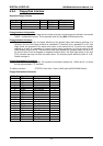
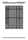
4.2. Addressing PCI Devices on the MSEBX800:
PCI Slot Assignment
The following definitions for the peripherals correspond with the BIOS:
Device IDSEL PIRQ REQ# GNT# Comments
SLOT 1 AD20 A, B, C, D 3 3
SLOT 2 AD21 B, C, D, A 4 4
SLOT 3 AD22 C, D, A, B 5 5
SLOT 4 AD23 D, A, B, C 6 6
LAN Controller AD29 A 7 7
ISA-Bridge AD24 -- 8 8
CS5536 AD25 --- 2 2 For VGA, IDE and USB
Arbiter 0 --- --- 0 0
Arbiter 1 --- --- 1 1