


DIGITAL-LOGIC AG MSEBX800/900 Detailed Manual V1.0
34
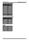
5.2.4. Floppy Disk Interface
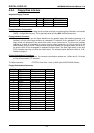
Supported Floppy Formats
Capacity Drive size Tracks Data rate DOS version
1.2 MB 5-1/4" 80 500 KHz 3.0 - 6.22
720 K 3-1/2" 80 250 KHz 3.2 - 6.22
1.44 M 3-1/2" 80 500 KHz 3.3 - 6.22
Floppy Interface Configuration
The desired configuration of floppy drives (number and type) must be properly initialized in the board's
CMOS – configuration memory. This is generally done by using DEL or F2 at bootup time.
Floppy Interface Connector
The table shows the pin-out and signal definitions of the board's floppy disk interface connector. It is
identical in pin-out to the floppy connector of a standard AT. Note that, as in a standard PC or AT, both
floppy drives are jumpered to the same drive select: as the 'second' drive. The drives are uniquely
selected as a result of a swapping of a group of seven wires (conductors 10-16) that must be in the
cable between the two drives. The seven-wire swap goes between the computer board and drive 'A';
the wires to drive 'B' are unswapped (or swapped a second time). The 26pin high density (1mm pitch
FCC) connector has only one drive and motor select. The onboard jumper defines the drive A: or B:.
Default is always A:.
Floppy Disk Interface Technology
Only CMOS drives are supported. This means the termination resistors are 1 KOhm and 5 1/4“-drives
are not recommended (TTL interface).
The 26pin connector: FFC/FPC 0.3mm thick 1.0mm (0.039") pitch (MOLEX 52030 Series)
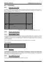
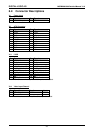
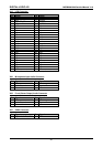
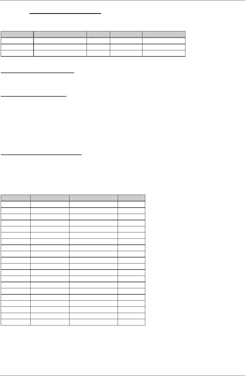
Floppy Disk Interface Connector
FD26: Pin Signal Name Function in/out
1 VCC +5Volt
2 IDX Index Pulse in
3 VCC +5Volt
4 DS2 Drive Select 2 out
5 VCC +5Volt
6 DCHG Disk Change in
10 MO2 Motor On 2 out
12 DIRC Direction Select out
14 STEP Step out
16 WD Write Data out
17 GND Signal grounds
18 WE Write Enable out
19 GND Signal grounds
20 TRKO Track 0 in
21 GND Signal grounds
22 WP Write Protect in
23 GND Signal grounds
24 RDD Read Data in
25 GND Signal grounds
26 HS Head Select out