


DIGITAL-LOGIC AG MSEBX800/900 Detailed Manual V1.0
50
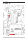
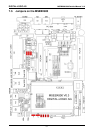
7. JUMPER LOCATIONS ON THE BOARD
The following tables show the location of the jumper blocks on the MSEBX800/900 board. The numbers
shown in these tables are silk screened on the board so that the pins can be easily located. This chapter
refers to the individual pins for these jumpers.
Be careful: some jumpers are soldering bridges; you will need a miniature soldering station with a vacuum
pump.
Settings written in bold are defaults!
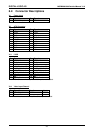
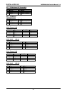
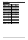
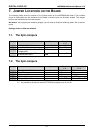
7.1. The 2pin Jumpers
Jumper Structure Open Closed
1 - 2
J2
LAN B (SM800DK LAN) isolate
Enable LAN B
Disable LAN B
J6
Select Video Out- or Input Enable LCD/LVDS
Enable Video-In
J8
Disable write protection of local FWH
(FirmWareHub)
FWH read only
FHW read / write
J9
Boot FWH from SM800PCX or from
the MSEBX800-Board
Boot SM800PCX
FWH
Boot local FWH
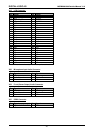
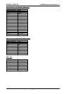
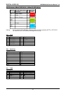
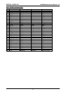
7.2. The 3pin Jumpers
Jumper Structure Open Closed
1 - 2
Closed
2 - 3
J1
PCI X130 slot in JTAG chain
JTAG w/
JTAG w/o
J3
LCD VDD voltage
+3.3V
+5V
J4
LVDS transmitter LVDS on LVDS auto on LVDS off
J5
LCD Backlight voltage +5V
+12V
1)
J7
RTC enable / disable
Enable RTC batt
Disable RTC batt
2)
1.) The 12V are only available if an ATX-Supply is connected.
2.) It's possible to connect an external RTC back-up battery to pin 2-3 of J7.