


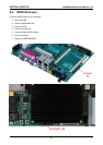
DIGITAL-LOGIC AG MSEBX800/900 Detailed Manual V1.0
39
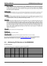
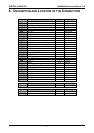
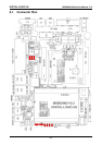
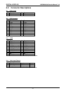
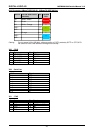
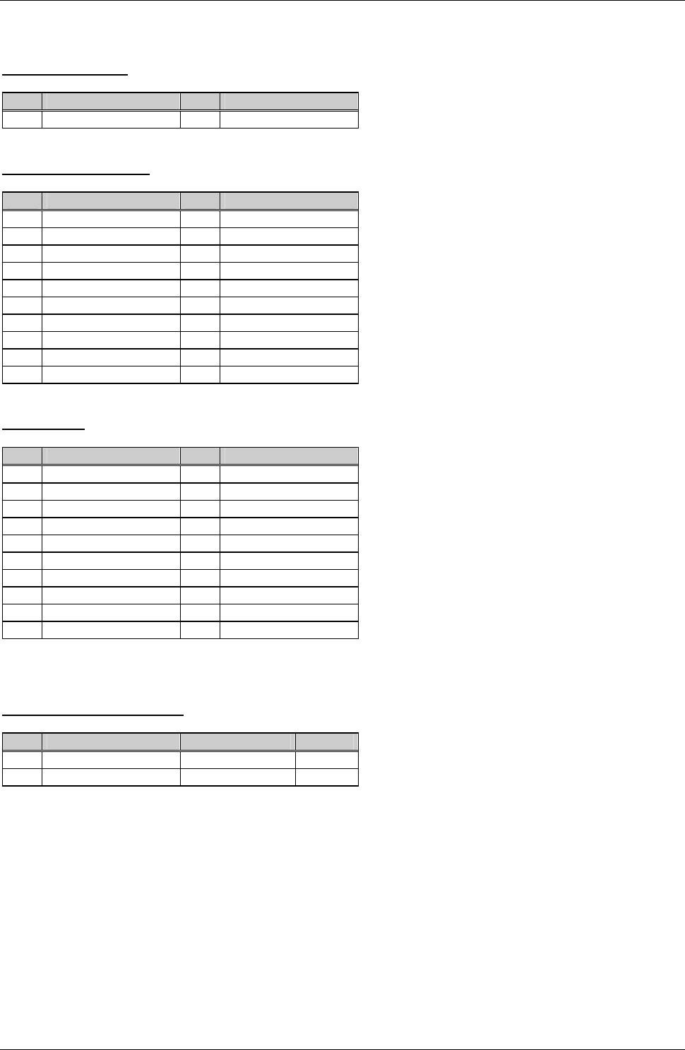
6.2. Connector Descriptions
X1 Power Input
Pin Signal Pin Signal
1 8-30V DC-Input 2 Ground
X2 ATX Connector
Pin Signal Pin Signal
1 +3.3V 2 +3.3V
3 GND 4 +5V
5 GND 6 +5V
7 GND 8 PWR-OK
9 +5VSB 10 +12V
11 +3.3V 12 -12V
13 GND 14 PS-ON#
15 GND 16 GND
17 GND 18 -5V
19 +5V 20 +5V
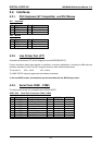
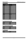
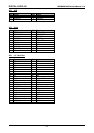
X11 LVDS
Pin Signal Pin Signal
1 LVDS_A0- 2 LVDS_A0+
3 GND 4 GND
5 LVDS_A1- 6 LVDS_A1+
7 LCD BKL (dep. J5) 8 LCD BKL (dep. J5)
9 LVDS_A2- 10 LVDS_A2+
11 LCD VDD (dep 3) 12 LCD VDD (dep 3)
13 LVDS_A3- 14 LVDS_A3+
15
NC
16
NC
17
NC
18
NC
19 LVDS_Clock- 20 LVDS_Clock+
The LVDS interface works only if the J6 Jumper is not installed.
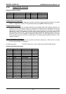
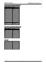
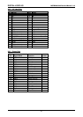
X14 Video Input Channel
Pin Signal Name Function in/out
1 Video Signal CVBS In
2 Ground
The Video IN interface works only if the J6 Jumper is installed.