


Removal and Replacement Procedures
3-3
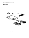
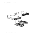
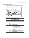
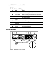
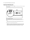
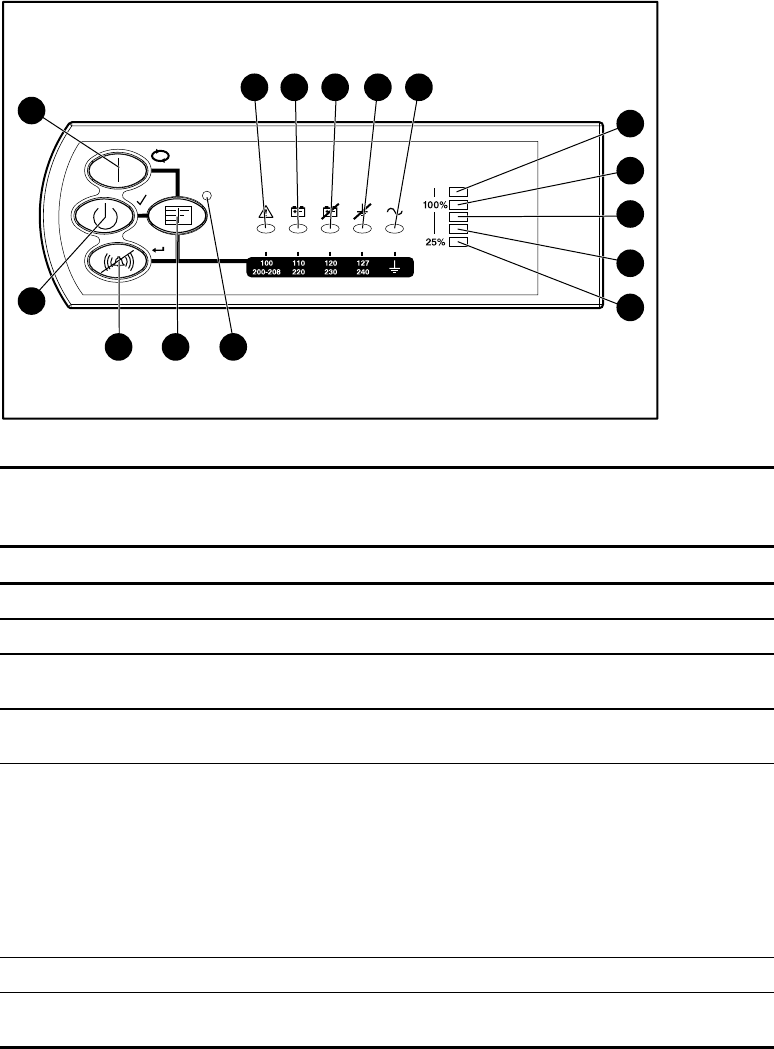
Front Panel Controls and LED Display
The UPS front panel contains four control buttons and ten LEDs that create the interface for
setup, configuration, load control, and status monitoring.
11
1 2 3
15
14
13
4 5
12
6
7
9
10
8
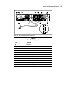
Figure 3-2. Front panel controls and LED display with front bezel removed
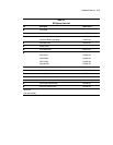
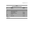
Table 3-2
Front Panel Controls and LED Display
Item Name Function
1
General Alarm Indicates a general alarm when red
2
On Battery Indicates that the battery is on when red
3
Bad Battery/Low
Battery
Indicates that the battery is bad or low when red
4
Site Wiring Fault
Indicator
Indicates a wiring fault when red
5
Utility LED Indicates that:
The unit is in Auto-Bypass mode when red
The utility voltage is present and output is on when green
The utility input voltage is outside nominal range when flashing red
The utility voltage is present and the UPS is in Standby mode when
flashing green
6
Overload LED Indicates that the UPS exceeds maximum power available when red
7
76% to 100% load Indicates that the UPS is approximately 76% to 100% of the maximum
power available when green
continued