


www.cooperbussmann.com/BussmannWirelessResources
15
Cooper Bussmann BU-245U-E Wireless Ethernet & Device Server User Manual
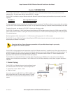
2.3 Serial Connections
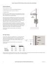
RS232 Serial Port
The serial port is a 9 pin DB9 female and provides for connection to a
host device as well as a PC terminal for configuration, field testing
and for factory testing. Communication is via standard RS232 signals.
The BU-245U-E is configured as DCE equipment with the pinouts
detailed below.
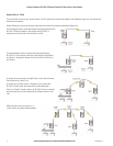
Hardware handshaking using the CTS/RTS lines is provided. The
CTS/RTS lines may be used to reflect the status of the local unit’s
input buffer. The BU-245U-E does not support XON/XOFF.
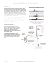
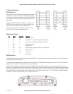
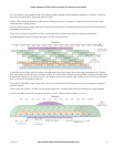
Example cable drawings for connection to a DTE host (a PC) or
another DCE hosts (or modem) are detailed above.
DB9 Connector Pinouts
Pin Name Direction Function
1 DCD Out Data carrier detect
2 RD Out Transmit Data – Serial Data Output (from DCE to DTE)
3 TD In Receive Data – Serial Data Input (from DTE to DCE)
4 DTR In Data Terminal Ready
5 SG - - Signal Ground
6 DSR Out Data Set Ready - always high when unit is powered on.
7 RTS In Request to Send
8 CTS Out Clear to send
9 RI - - Ring indicator
RS485 Serial Port
The RS485 port provides for communication between the BU-245U-E unit and its host device using a multi-drop cable. Up to 32 devices may be
connected in each multi-drop network.
As the RS485 communication medium is shared, only one of the units on the RS485 cable may send data at any one time. Thus, communication
protocols based on the RS-485 standard require some type of arbitration.
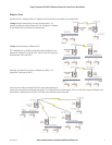
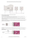
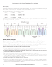
RS485 is a balanced, differential standard but it is recommended that shielded, twisted pair cable be used to interconnect modules to reduce
potential RFI. It is important to maintain the polarity of the two RS485 wires. An RS485 network should be wired as indicated in the diagram below
and terminated at each end of the network with a 120-ohm resistor. On-board 120-ohm resistors are provided and may be engaged by operating
the single DIP switch in the end plate next to the RS485 terminals. The DIP switch should be in the “1” or “ON” position to connect the resistor. If
the module is not at one end of the RS485 cable, the switch should be OFF.
3A1576Rev1.6