


56
www.cooperbussmann.com/BussmannWirelessResources
Cooper Bussmann BU-245U-E Wireless Ethernet & Device Server User Manual
All Modbus Master messages are directed to/from the onboard I/O registers depending on configuration (described below).
The Modbus TCP Client may also poll Modbus RTU (i.e., serial) devices connected to either the local serial port or a remote BU-245U-E serial
port by enabling the Modbus TCP to RTU gateway at the corresponding serial port (see section 3.16 “Serial Port Configuration”).
Modbus TCP Client functionality allows connections to a maximum of 25 different Modbus
TCP Servers.
Modbus TCP Server (Slave) enables the BU-245U-E to accept connections from one or
more Modbus TCP Clients (Masters).
All Modbus transactions routed to the onboard Modbus TCP Server are directed to/from
the onboard general purpose I/O registers. The Modbus TCP Server is shared with the
Modbus TCP to RTU Gateway, so that the Modbus “Device ID” is used to determine if a
Modbus transaction is to be routed to the onboard Modbus TCP Server or to a Modbus
RTU device connected to the serial port. Care should therefore be taken that all serially
connected Modbus devices use a different Modbus Device ID (i.e., Modbus Slave Address)
to the onboard Modbus TCP Server. Up to 32 separate connections to the Modbus TCP
Server are supported.
Modbus RTU (serial) Master functionality is achieved by combining the Modbus TCP Client (Master) and Modbus TCP to RTU Gateway. Simply
specify a Modbus TCP Client (Master) connection to a Modbus TCP Server where the server is the address of any BU-245U-E with Modbus TCP to
RTU Gateway enabled. Care should be taken to ensure that the Device ID (i.e., Modbus Address) of the serial device is different to the Device ID of
the onboard Modbus TCP Server of the BU-245U-E that the serial device is connected to.
The BU-245U-E provides a configurable option to automatically reset the value of the onboard I/O registers to zero in the event of a
communications failure. If a valid Modbus transaction directed to/from a given register has not been completed for longer than a configurable
timeout, then the value of that register will be reset to zero.
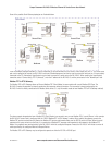
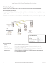
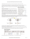
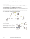
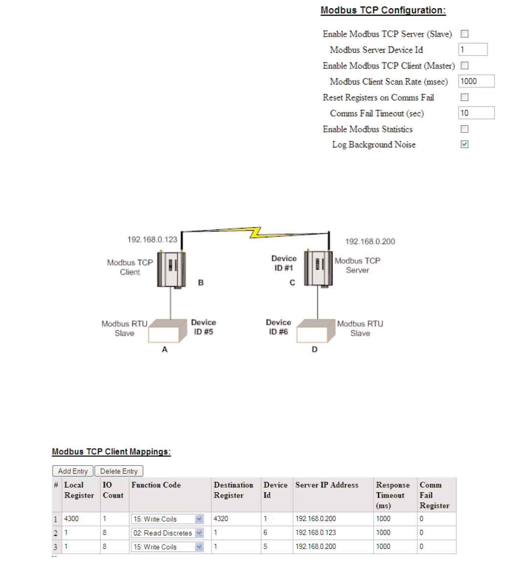
An example of the Modbus functionality of the BU-245U-E is illustrated below. In this example the status of the onboard digital input at C will be
reflected at the onboard digital output at B. Also, 8 single bit registers from Modbus serial device D will be transferred to A.
Unit B is configured with Modbus TCP Server enabled and Device ID = 1, Unit C is configured as shown above.
3A1576Rev1.6