


38
www.cooperbussmann.com/BussmannWirelessResources
Cooper Bussmann BU-245U-E Wireless Ethernet & Device Server User Manual
WDS bridge interfaces have the advantage that redundant paths are permitted when using the bridge Spanning Tree Protocol (see section 3.11
“Spanning Tree Algorithm”), thus behaving as a self-healing mesh network. Bridged networks are also not as configuration intensive as routed
networks. Since WDS bridge interfaces generally do not require IP address configuration (they inherit the IP address of the standard
wireless interface).
A WDS router interface allows traffic to be routed to an Access Point on a different network, and therefore requires configuration of an IP address
to reflect the network address of the destination network. WDS router interfaces cannot provide the redundancy of bridge interfaces, but can be
used to reduce radio bandwidth requirements because the router can determine the destination based on IP address, whereas the bridge must go
through a learning phase where all broadcast traffic must be retransmitted on each interface. Routed networks may also be used in some cases
to avoid the overhead introduced by the bridge Spanning Tree Protocol when network loops exist.
Each WDS interface may also be configured with a different encryption algorithm; however each side of a single WDS link must specify the same
encryption algorithm and keys.
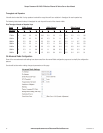
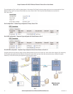
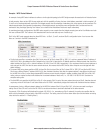
Specify SSID for AP/STA modes or MAC Address for Point to point mode.
Router IP and Subnet should be left blank unless that WDS interface is to be on a different subnet. Leaving these fields blank will mean that the
WDS interface will be bridged with the default wireless interface.
When adding WDS router interfaces, you may also need to add a Routing Rule on the Routing configuration page.
Spanning Tree Protocol (STP) column only applies when two or more interfaces are bridged.
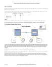
A maximum of 10 WDS Connections can be configured. (A combined maximum of 5 AP and STA virtual modules applies.)
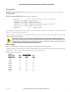
WDS Connections are made by adding one or more “Virtual Modules” to an Access Point (as illustrated in the diagram at the start of the section).
Each virtual module can be configured with one of the standard wifi operating modes (Access Point or Station) or a non-standard Point to Point
mode.
• Access Point and Station virtual modules allow for the possibility of dynamically created connections (based on SSID) and support WPA
Encryption. A combined maximum of 5 AP and STA virtual modules can be configured per unit.
• Point to point mode virtual modules provide static connections (based on MAC addresses), and cannot support WPA Encryption. Point to point
virtual modules should only be used for establishing WDS connections with third party Access Points that do not support standard
WDS operation.
All Access Points must be configured on the same fixed radio channel. Auto Channel selection must not be selected (See “Radio”
page for details on configuring the channel.)
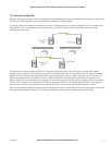
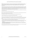
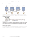
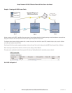
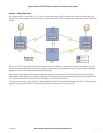
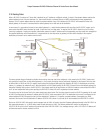
There are many different ways to setup wireless networks; often it depends on the devices you wish to connect and the existing network topology.
The following pages show some examples of how to connect devices into different types of systems.
3A1576Rev1.6