


www.cooperbussmann.com/BussmannWirelessResources
Cooper Bussmann BU-905U-L Wireless I/O Installation Manual
NOTE:
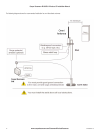
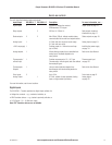
1. Cooper Bussmann recommends using the 905U-G module as a repeater unit between BU-905U-L-T and BU-905U-L-R modules.
2. To use a repeater unit, the BU-905U-L modules and the repeater module must be configured using the supplied configuration software. The
factory default configuration described in the Quick Start Guide cannot use a repeater unit.
Installing and Earthing Antennas
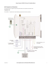
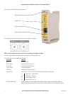
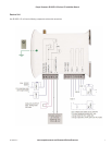
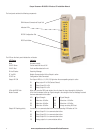
You must connect an antenna to each BU-905U-L module using the SMA connector at the top of the enclosure.
Cooper Bussmann recommends carefully taping the connections between the antenna and coaxial cable to prevent moisture ingress. Moisture
ingress in the coaxial cable is a common cause of radio system problem as it greatly increases the radio losses.
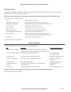
Cooper Bussmann recommends taping the connection with three layers of tape:
Layer Tape
1 PVC tape.
2 Vulcanizing tape (e.g. 3M 23 tape).
3 Additional layer of PVC UV-stabilized insulating tape.
The first tape layer lets you easily inspect the joint if required as you can easily remove the Vulcanizing seal.
Note: You must effectively earth all masts for mast-mounted antennas to avoid lightning surges. We also recommend using a coaxial
surge diverter for antennas mounted outside industrial plant environments.
If the antenna is not already shielded from lightning strike by an adjacent earthed structure, you can provide shielding by installing a lightning rod
above the antenna.
You should connect the antenna to the module using 50 ohm coaxial cable (e.g. RG58 or RG213) terminated with a male coaxial connector, The
higher the antenna is mounted, the greater the transmission range; however as the length of coaxial cable increases so do cable losses. For use
on unlicensed frequency channels, there are several types of antenna suitable for use.
If you mount antennas on elevated masts, you should effectively earth the masts to avoid lightening surges. The BU-905U-L radios are fitted with
surge protection.
Note: For high lightening risk areas, Cooper Bussmann recommends additional surge suppression devices. If the antenna is not
already shielded from lightening strike by an adjacent earthed structure, you can install a lightening rod to provide shielding.
Omni-directional Antennas
This section contains important information for using dipole and collinear antennas. For more information, see the next sections.
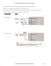
Dipole Antennas
Unity gain dipole antennas are commonly used on unlicensed channels. The dipole antenna does not provide any gain, so the power transmitted
from the antenna is the same as the power out of the module.
A dipole antenna that comes supplied with integral 15 ft cable does not require additional coaxial cable.
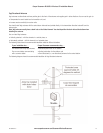
You should mount dipole antennas vertically, preferably no less than 1 metre away from a wall or mast for maximum performance.
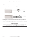
Collinear Antennas
Collinear antennas transmit the same amount of radio power in all directions horizontally, and are easy to install and use. They provide gain by
compressing the radiated signal to a flattened disc shape, and reducing the amount of signal radiated above and below the horizontal plane.
Collinear antennas are generally used at a central site with more than one remote site, or at a repeater site.
Collinear antennas are similar in appearance to dipole antennas; however the antenna is longer.
Collinear antennas are supplied without cable, and require additional coaxial cable.
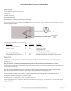
You can use collinear antennas to:
• Transmitter – to compensate for the losses in long lengths of coaxial cable.
• Receiver – to increase receive sensitivity.
113A1580Rev1.6