


www.cooperbussmann.com/BussmannWirelessResources
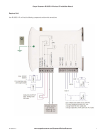
Cooper Bussmann BU-905U-L Wireless I/O Installation Manual
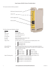
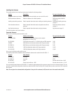
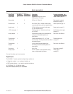
INPUTS AND OUTPUTS
The units have the following inputs and outputs:
Input/Output BU-905U-L-T BU-905U-L-R Description For more information, see …
Digital inputs 2 Suitable for Voltage free contact, Digital inputs on page 15.
NPN transistor, 0-5V signal.
Relay outputs 3 250Vac 1A / 30Vdc 1A. Relay outputs Important
Information on page 17.
Status outputs 2 2 Max 30Vdc, 500mA. Indicate module status, Status outputs on page 18.
communication failure and local setpoint status.
Analog inputs 1 4-20mA with over-range and under-range. Analog input on page 18.
0-10mA with over-range.
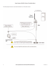
+24V Loop supply 1 Provides power for 1 external current loop Installing the power supply
(up to 35mA). on page 14.
Analog setpoint 1 Allows discrete setpoint to be controlled from Refer to the User Manual.
analog input. Threshold adjustable via
rotary switch.
Thermocouple / 1 Provides measurement of E, J, K, T type Thermocouple input
millivolt input Thermocouple, millivolt signals and user-defined on page 20.
thermocouple types.
Thermocouple 1 Lets you control discrete setpoint from Refer to the User Manual.
Setpoint thermocouple with threshold adjustable via
rotary switch.
Pulse inputs 2 Up to 10Hz. Pulse input on page 21.
Analog Output 1 0-22mA, suitable for loop powered, floating Analog output
input or single-ended input device. on page 22.
For more information, see the next sections.
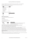
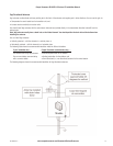
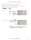
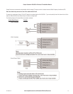
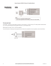
Digital Inputs
The BU-905U-L-T module provides two digital inputs suitable for:
• Voltage free contacts – e.g., mechanical switches; or
• NPN Transistor devices – e.g., electronic proximity switches; or
• 0-5V Signals - 2V – 4V Minimum range.
Note: PNP Transistor devices are not suitable.
153A1580Rev1.6