


14
www.cooperbussmann.com/BussmannWirelessResources
Cooper Bussmann BU-905U-L Wireless I/O Installation Manual
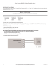
Installing the Power Supply
The unit works with a 9-30Vdc 0.6 Amp CSA certified Class 2 power supply. For use in Class 1 Div 2 hazardous locations, the power supply must
be approved for Class 1 Div 2 use.
Warning – Explosion Hazard
Do not disconnect while circuit is live unless area is known to be non-hazardous.
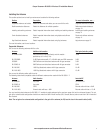
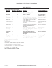
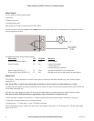
The following table shows the power supply requirements:
Power Supply BU-905U-L-T BU-905U-L-R
12V 600mA 250mA
24V 300mA 125mA
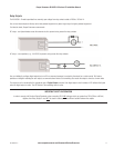
The power supply can be a floating supply or negatively grounded.
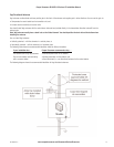
The transmitter provides a 24Vdc regulated supply for analog loop power. The supply is rated at 35mA and should ONLY be used for powering
analog loops.
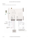
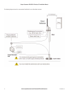
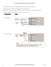
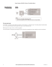
To install the power supply:
1. Connect the positive lead to Power Supply Input.
2. Connect the negative lead to Ground.
Note: To ensure internal surge protection works correctly, you must earth each unit using the Earth terminal.
- You should connect the module to the same ground/earth point as the antenna mounting to avoid
differences in earth potential during voltage surges.
- Do NOT connect the positive side of the supply to Earth.
3. The following diagram illustrates the connection:
3A1580Rev1.6