


CRADLEPOINT IBR650 | USER MANUAL Firmware ver. 3.3.0
© 2011 CRADLEPOINT, INC. PLEASE VISIT HTTP://KNOWLEDGEBASE.CRADLEPOINT.COM/ FOR MORE HELP AND RESOURCES PAGE 107
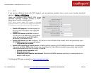
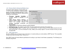
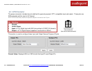
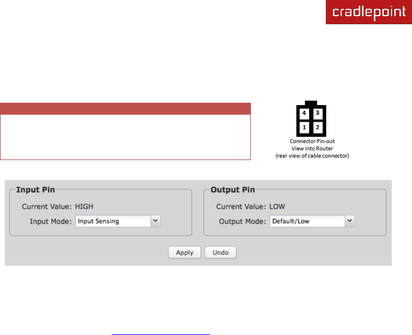
8.3 GPIO Connector
The power connector includes two pins defined for general purpose LVTTL compatible input and output. These pins are
ESD protected and the input is 5V tolerant.
NOTE: GPIO functionality requires a separate adapter to connect to the I/O pins.
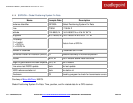
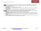
Pin
Definition
1
Ground
2
12VDC Power
3
Input: LVTTL Digital Input with 50K ohm pullup to 3.3VDC (5V tolerant)
4
Output: LVTTL Digital Output (capable of source/sink of 50mA)
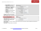
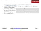
This section is used to configure these Input and Output General Purpose I/O pins.
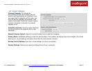
Current Value: Displays HIGH or LOW for both the Input Pin and Output Pin.