


Crestron C2N-SPWS300 System Power Supply
Operations Guide – DOC. 8190 System Power Supply: C2N-SPWS300 • 7
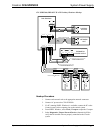
Network Wiring
CAUTION: Use only Crestron power supplies for Crestron equipment. Failure to
do so could cause equipment damage or void the Crestron warranty.
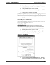
NOTE: When installing network wiring, refer to the latest revision of the wiring
diagram(s) appropriate for your specific system configuration, available from the
Downloads | Product Manuals | Wiring Diagrams section of the Crestron website
(www.crestron.com)
.
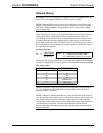
When calculating the wire gauge for a particular network run, the length of the run
and the power factor of each network unit to be connected must be taken into
consideration. If network units are to be daisy-chained on the run, the power factor
of each network unit to be daisy-chained must be added together to determine the
power factor of the entire chain. The length of the run in feet and the power factor of
the run should be used in the following resistance equation to calculate the value on
the right side of the equation.
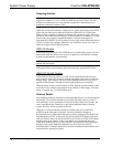
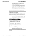
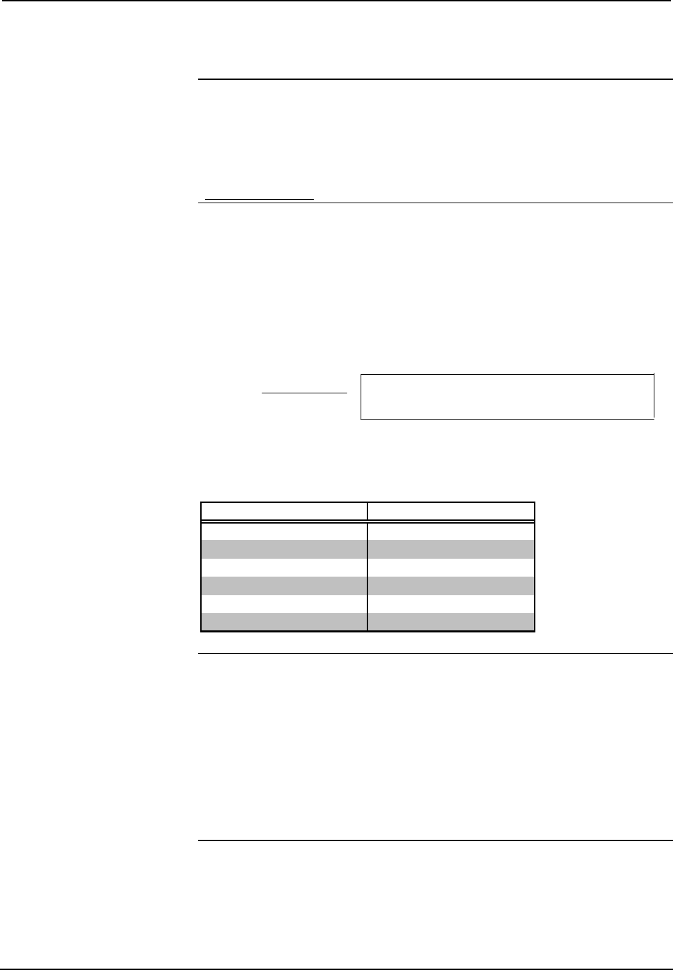
Resistance Equation
R = Resistance (refer to table below).
L = Length of run (or chain) in feet.
PF = Power factor of entire run (or chain).
R <
L x PF
40,000
Where:
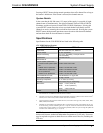
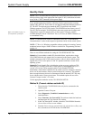
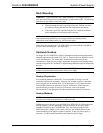
The required wire gauge should be chosen such that the resistance value is less than
the value calculated in the resistance equation. Refer to the table after this paragraph.
Wire Gauge Values
RESISTANCE (R) WIRE GAUGE
4
16
6
18
10
20
15
22
13
Doubled CAT5
8.7
Tripled CAT5
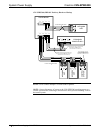
NOTE: All network wiring must consist of two twisted-pairs. One twisted pair is
the +24V conductor and the GND conductor and the other twisted pair is the Y
conductor and the Z conductor.
NOTE: When daisy chaining network units, always twist the ends of the incoming
wire and outgoing wire that share a pin on the network connector. After twisting the
ends, tin the twisted connection with solder. Apply solder only to the ends of the
twisted wires. Avoid tinning too far up or the tinned end becomes brittle and breaks.
After tinning the twisted ends, insert the tinned connection into the network
connector and tighten the retaining screw. Repeat the procedure for the other three
network conductors.