


System Power Supply Crestron C2N-SPWS300
4 • System Power Supply: C2N-SPWS300 Operations Guide - DOC. 8190
Physical Description
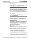
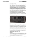
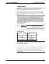
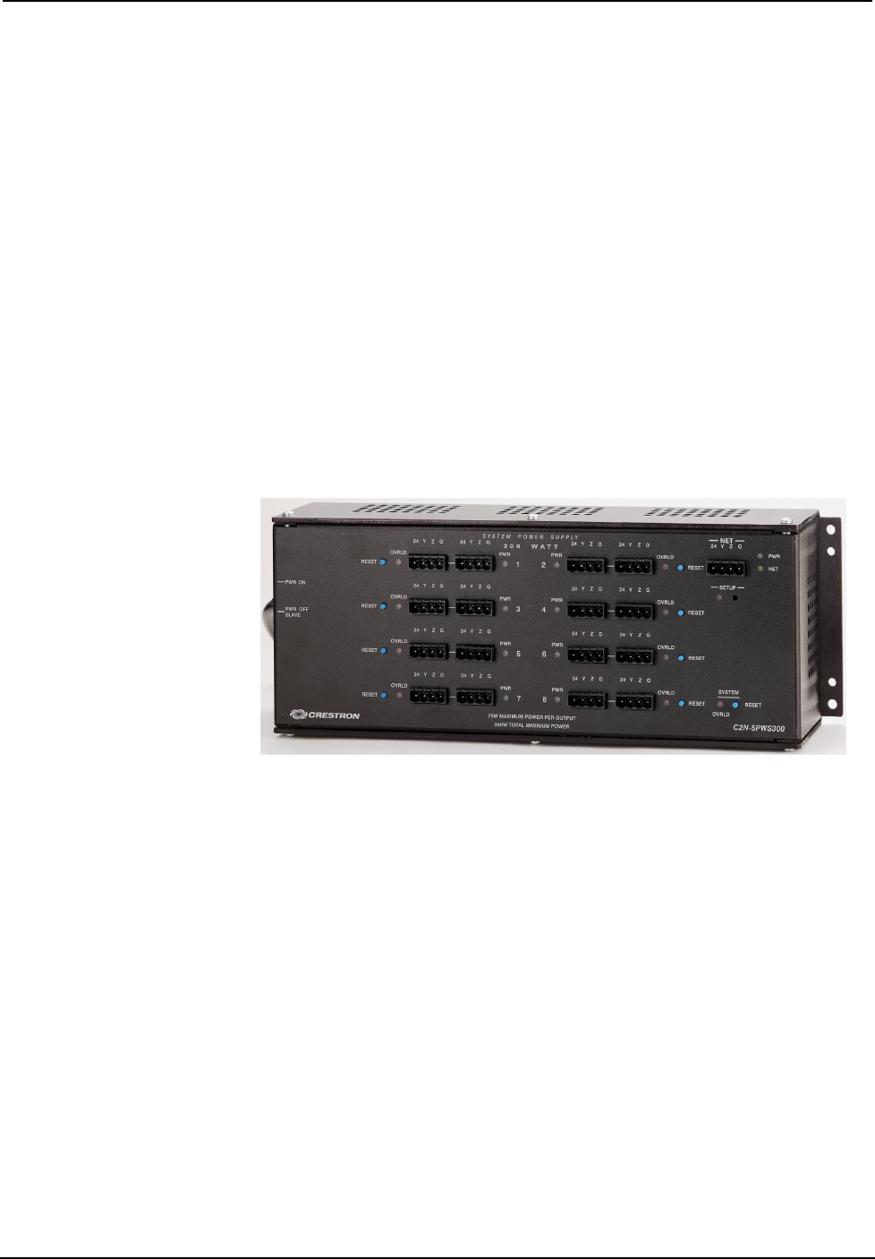
The C2N-SPWS300, shown after this paragraph, is housed in a sturdy 1/8-inch black
anodized aluminum enclosure. A power selection switch and pigtail input power
cable with an IEC320 socket are located to the left side of the unit. A screened
overlay covers the front panel. The front panel has 17 four-pin network connectors.
The data lines (Y and Z pins) on all network connectors are internally wired in
parallel. One network connector in the upper right corner of the front panel must
connect to a Crestron
control system when the power switch is in the POWER OFF
SLAVE position. Power and network LEDs support this connector. The other 16
network connectors are divided into eight pairs. Each pair is a channel used for
integration of the unit into the Cresnet system. Each of the eight channels also has an
overload and power LED as well as a reset button. In the lower right corner of the
front panel there is an overload LED and reset button for the system. A recessed
setup switch and LED are located above the system LED and button.
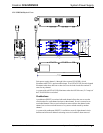
This power supply has been designed to mount horizontally on its back in a rack
cabinet or on a wall. At the shorter sides of the unit, the enclosure extends at a right
angle to provide mounting flanges equipped with screw holes (hardware supplied by
others).
C2N-SPWS300 System Power Supply
Ports
With the exception of the IEC320 connector on a pigtail cord (for application of AC
power), all connections to the C2N-SPWS300 are made via the ports on the front
panel.
The single four-pin network connector in the upper right corner on the front panel is
used to accept 24 VDC when the power switch is set to the PWR OFF SLAVE
position. Data provided to this connector is made available to all other network
connectors since the data signals are in parallel. Refer to “Network Wiring” on page
7.
The eight pairs of four-pin network connectors centrally located on the front panel
are provided for distribution of power and data signals. Data and ground pins are
internally wired in parallel from channel to channel. Each pair or channel is capable
of delivering a nominal 75 watts of power at 24 VDC.
Indicators
A green LED (PWR) in the upper right corner of the front panel illuminates when the
internal 300-watt power supply is enabled. Refer to “Powering the Unit” on page 2
for details. The yellow LED (NET) located below the PWR LED illuminates when
the program running in the Crestron control system polls the unit.