


Crestron C2N-SPWS300 System Power Supply
Operations Guide – DOC. 8190 System Power Supply: C2N-SPWS300 • 11
Rack Mounting
WARNING: To prevent bodily injury when mounting or servicing this unit in a
rack, take special precautions to ensure that the system remains stable. The following
guidelines are provided to ensure user safety.
• When mounting this unit in a partially filled rack, load the rack from
the bottom to the top with the heaviest component at the bottom.
• If the rack is provided with stabilizing devices, install the stabilizers
before mounting or servicing the units in the rack.
NOTE: Reliable grounding of rack-mounted equipment should be maintained.
Particular attention should be given to supply connections other than direct
connections to the branch circuit (e.g., use of power strips).
Material for rack mounting the C2N-SPWS3000 is provided with the C2N-RMAK
(Crestron Rack Mounting Kit – sold separately).
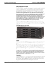
Hardware Hookup
By design, the C2N-SPWS300 is rated to withstand elevated operating temperatures
(internal temperatures can reach 122°F (50°C)). Therefore, the unit should be used in
a well-ventilated area. The venting holes should not be obstructed under any
circumstances. When the power supply approaches its maximum temperature rating,
consider using forced air ventilation or implementing additional supplies to distribute
the load.
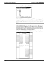
NOTE: Utilize the signals available from the C2N-SPWS300 SIMPL Windows
symbol to track the internal temperature of the power supply.
Hookup Preparation
Prior to making hardware connections, it is assumed that all wiring is run and
terminated with network connectors. However, the network connectors should not
yet be plugged into the network units. Use an ohmmeter to verify that none of the
four network conductors are shorted or crossed. Furthermore, ensure that each
network unit has its unique ID code set. If necessary, refer to the product
documentation for the appropriate ID code assignment procedure of each device.
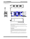
Hookup Methods
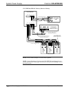
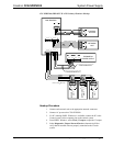
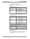
NOTE: Loads should be connected to the eight channels so that all of the channels
are utilized and loads are distributed as evenly as possible.
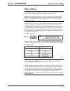
Whether the power switch is set to the PWR ON or PWR OFF SLAVE position, the
hookup diagrams, after this paragraph, illustrate the home run and daisy chain
methods of connecting the C2N-SPWS300. They also illustrate multiple C2N-
SPWS300s within a single Cresnet system. Only use the methods shown; do not
connect multiple power supplies together in parallel. If only one power supply is
necessary, use either method and remove the expansion power supply.