


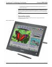

Crestron DTT-15V3 DualTouch™ Technology Touchpanel
Operations Guide – DOC. 6632B DualTouch™ Technology Touchpanel: DTT-15V3 • 7
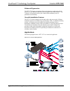
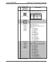
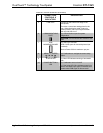
Connectors, Controls & Indicators
# CONNECTORS,
CONTROLS &
INDICATORS
DESCRIPTION
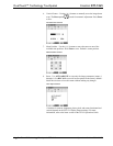
1
USB
Pin 1
Pin 3Pin 2
Pin 4
(1) USB B female; USB 2.0 port;
Connects to any USB port on UPX-2 using
6 ft (2.0 m) USB cable (included)
PIN DESCRIPTION
1 +5 VDC
2 Data -
3 Data +
4 Ground
2
DC IN (12V)
(1) DC power jack (power supply included)
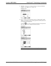
3
ANALOG RGB OUT
(1) DB15HD female;
RGB (VGA) video loop-thru;
Passes RGB input through to an additional
display device
Pin 1 Red Video
Pin 2 Green Video
Pin 3 Blue Video
Pin 4 Reserved
Pin 5 Ground
Pin 6 Red Ground
Pin 7 Green Ground
Pin 8 Blue Ground
Pin 9 No Connect
Pin 10 Ground
Pin 11 No Connect
Pin 12 No Connect
Pin 13 Horizontal Sync
Pin 14 Vertical Sync
Pin 15 No Connect
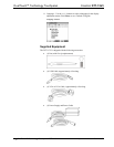
4
ANALOG RGB IN
(1) DB15HD female; RGB (VGA) video
input;
Connects to RGB Output A of UPX-2 using
6 ft (2.0 m) DB15HD VGA cable (included)
Pin 1 Red Video
Pin 2 Green Video
Pin 3 Blue Video
Pin 4 Reserved
Pin 5 Ground
Pin 6 Red Ground
Pin 7 Green Ground
Pin 8 Blue Ground
Pin 9 No Connect
Pin 10 Ground
Pin 11 No Connect
Pin 12 Monitor Sense
Pin 13 Horizontal Sync
Pin 14 Vertical Sync
Pin 15 Monitor Sense Clock
(Continued on following page)