


DualTouch™ Technology Touchpanel Crestron DTT-15V3
8 • DualTouch™ Technology Touchpanel: DTT-15V3 Operations Guide – DOC. 6632B
Connectors, Controls & Indicators (Continued)
# CONNECTORS,
CONTROLS &
INDICATORS
DESCRIPTION
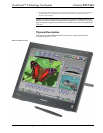
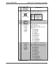
5 PEN TRAY
Located on the bottom front edge of the
touchpanel;
Provides a convenient resting place for the
pen. When the display stand is set to its
lowest position, place your fingers beneath
the tray and slide it out.
6
COMMUNICATIONS
PORT
(2) Communications port for system
diagnostics;
CAUTION: Do not connect any devices to this
port.
7
USB
MOUSE/KEYBOARD
(2) USB Type A female
USB 2.0 hub ports for mouse/keyboard (not
included)
Device Power: 500 mA maximum per port
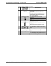
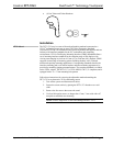
8
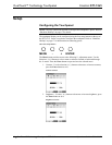
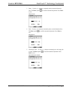
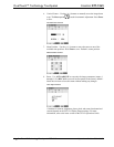
MENU, -, +, ENTER
(4) Pushbuttons to navigate onscreen setup
menu
9 STATUS LED
(1) Blue LED indicates sensing of annotation
pen
10
POWER BUTTON &
LED
(1) Pushbutton turns unit on/off
(1) Dual-color LED; Blue indicates power is on
with a valid RGB input signal connected; turns
amber when RGB signal is disconnected