


Crestron DTT-15V3 DualTouch™ Technology Touchpanel
Operations Guide – DOC. 6632B DualTouch™ Technology Touchpanel: DTT-15V3 • 17
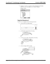
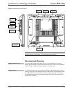
Hardware Hookup
Refer to the following diagram and complete the connections as specified. Ensure
that the UPX-2 and the DTT-15V3 are both powered down before beginning.
CAUTION: To avoid damage to the DTT-15V3 or to your video card, never
connect or disconnect the video or power cable while the DTT-15V3 or the UPX-2
are powered up.
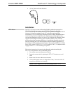
NOTE: The USB cable may be extended using up to four 16-foot active extensions.
Each extension cable must contain a hub (repeater) to regenerate the USB signal
(maximum of 64 feet). For longer extensions, Crestron has tested and approved
IOGEAR USB Extender model GUCE50, which allows up to 150 feet over CAT5.
NOTE: Using high quality cable, the VGA cable may be extended up to a
maximum of about 10 meters (32.8 ft.) for analog VGA at 1024 x 768. If you need a
longer run, add VGA extenders or VGA distribution amplifiers.
1. Connect the RGB/VGA cable, linking the UPX-2 RGB OUTPUT A
connector to the DTT-15V3 RGB VIDEO IN connector.
2. Connect the USB cable, linking the UPX-2 USB port to the DTT-15V3
USB port.
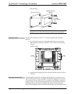
3. Connect the power supply line cord to an AC outlet and the power supply
adaptor.
4. Plug the power adaptor cord into the DTT-15V3 DC IN port.
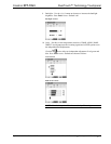
5. Power up the DTT-15V3. The power indicator should light up amber.
6. Power up the UPX-2. When a video signal is applied to the DTT-15V3, the
power indicator will turn blue.