


CyberResearch
®
CPU Cards CPEx GX-333-X
CyberResearch, Inc. 27
25 Business Park Drive P: (203) 483-8815; F: (203) 483-9024
Branford, CT USA www.cyberresearch.com
10mA load on the 5V source standby lead for this function to take effect. If the LAN Wake-on
function should be applied, a minimum of 650mA should be supplied.
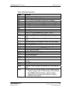
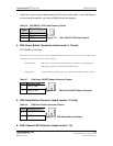
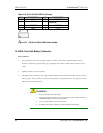
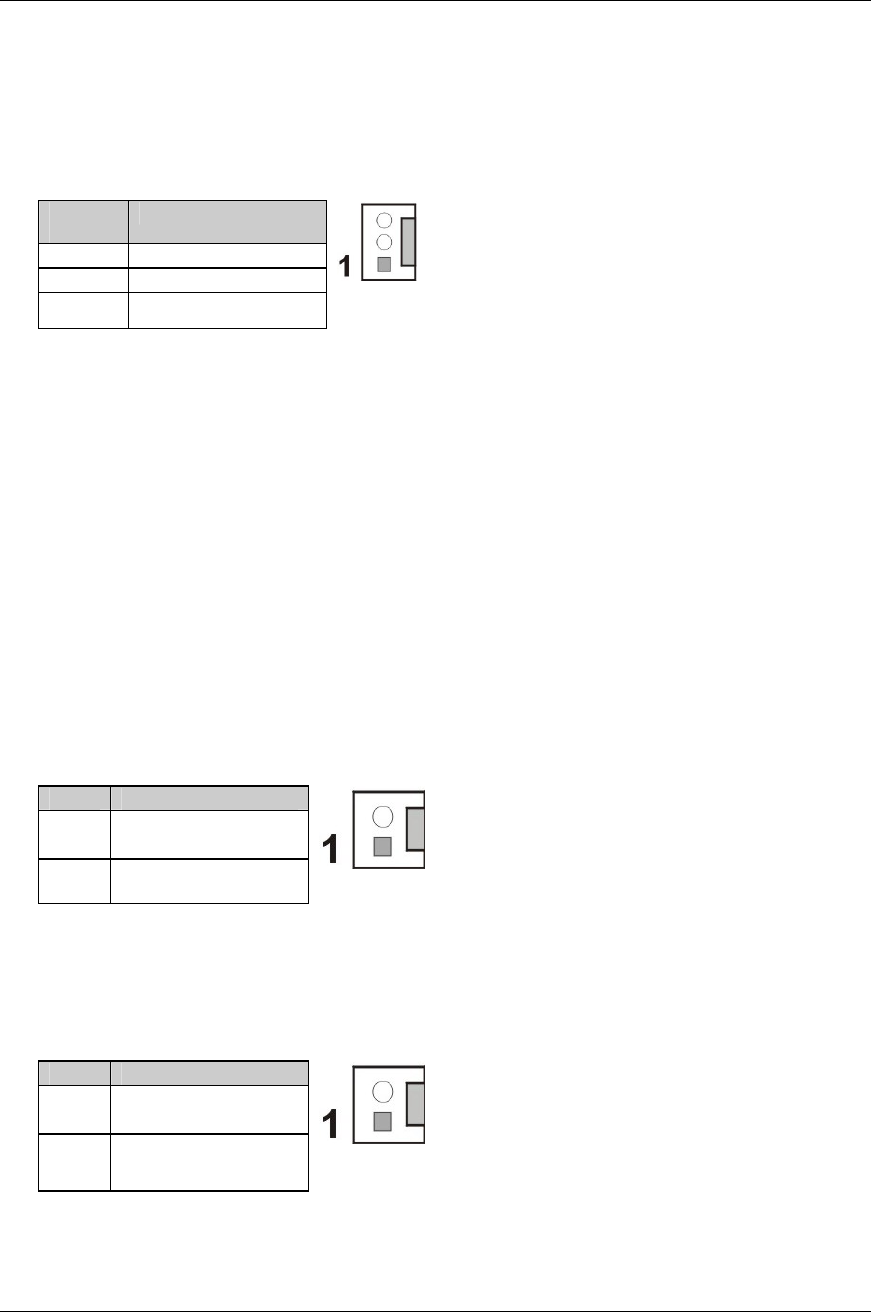
Table 2-6 CN3 SBVCC: ATX Power Feature Pinouts
PIN
DESCRIPTION
1 GND
2 PS_ON
3 5VSB
Figure 2-11 CN3 - SBVCC ATX Power Feature
4. CN4: Power Button Connector (board version 1.10 only)
JST HEADER 1x2 2.54mm
This connector is used to connect a chassis power On/Off button using an adapter cable. This connector is closely related to JP2
configuration. The use of this connector is briefed as follows:
1. Using ATX power: CN4 connects to a power switch which functions as a soft-power-on switch managed by
BIOS power-on setting, and the JP2 jumper should be left open.
2. Using AT power: The pins on JP2 are shunted by a jumper cap. The default configuration of JP2 is shunted.
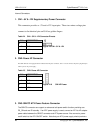
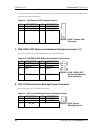
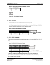
Table 2-7 CN4 Power ON/OFF Button Connector Pinouts
PIN DESCRIPTION
1
AUTO_SW#
2 PWR_BTN#
Figure 2-12 CN4 Power ON/OFF Button Connector
5. CN5: Reset Button Connector (board version 1.10 only)
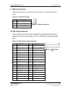
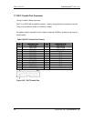
Table 2-8 CN5 Reset Button Connector Pinouts
PIN DESCRIPTION
1
SYS_RST#
2 GND
Figure 2-13 CN5 Reset Button Connector
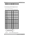
6. CN6: Chassis LED Connector (board version 1.10)