


CPEx GX-333-X CyberResearch
®
CPU Cards
28 ©Copyright 2007 CyberResearch, Inc.
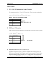
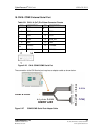
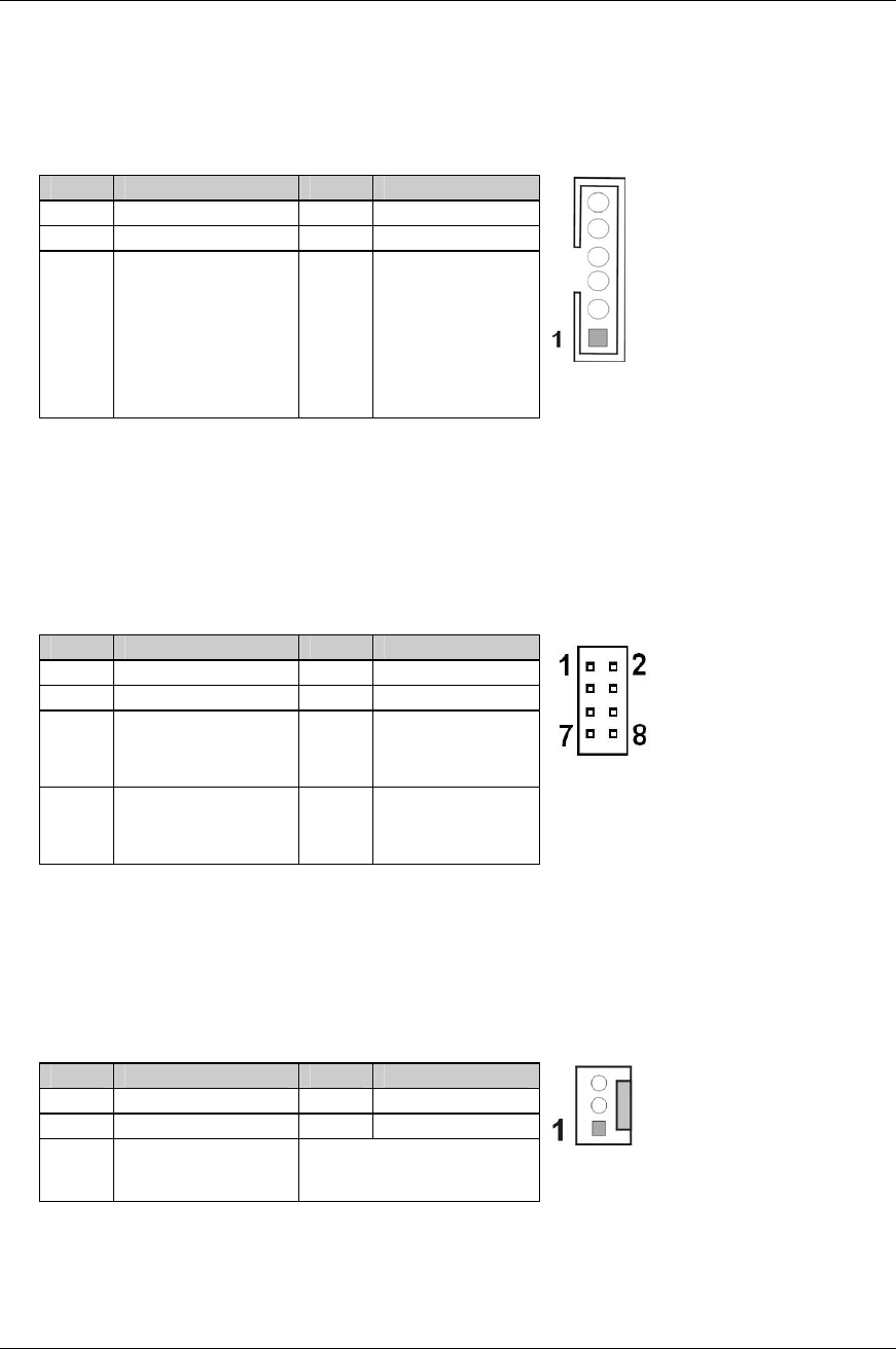
This connector comes as a 1x6 pin Wafer 2mm connector. This connector facilitates the connection from SBC to chassis LEDs
through the chassis LED controller board.
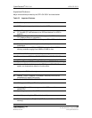
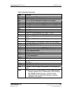
Table 2-9 CN6 Chassis LED Connector Pinouts
PIN DESCRIPTION PIN DESCRIPTION
1 +5V 2 GND
3 LED+ (VCC) 4 LED- (GND)
5 IDE_LED+ (VCC) 6 IDE_LED-
Figure 2-14 CN6 - Chassis LED
Connector
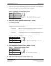
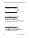
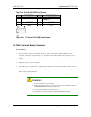
7. CN6: PWR & RST Button and Indicators Panel (board version 1.11)
The Connector includes a Power Button & Reset Button, a Power LED and IDE LED.
Table 2-10 CN6 PWR & RST Button and Indicators Panel Pinouts
PIN DESCRIPTION PIN DESCRIPTION
1 PWRBTN 2 +5V
3 GROUND 4 GROUND
5 +5V 6 RESET
7 HDDLED- 8 GROUND
Figure 2-15 CN6 - PWR & RST
Button and Indicators
Panel Connector
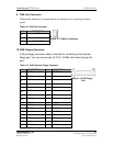
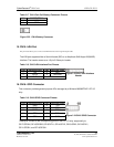
8. CN7: LCD Panel Inverter Backlight Control Connector
This connector comes as a 1x5 pin Wafer 2mm connector.
Table 2-11 CN7 Inverter Backlight Control Connector Pinouts
PIN DESCRIPTION PIN DESCRIPTION
1 LCD_ADJ 2 GND1
3 +12V 4 GND2
5 BL_EN -
Figure 2-16 CN7 Inverter
Backlight Control