CY7C0430BV
CY7C0430CV
Document #: 38-06027 Rev. *B Page 11 of 37
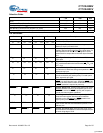
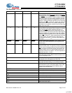
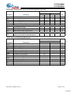
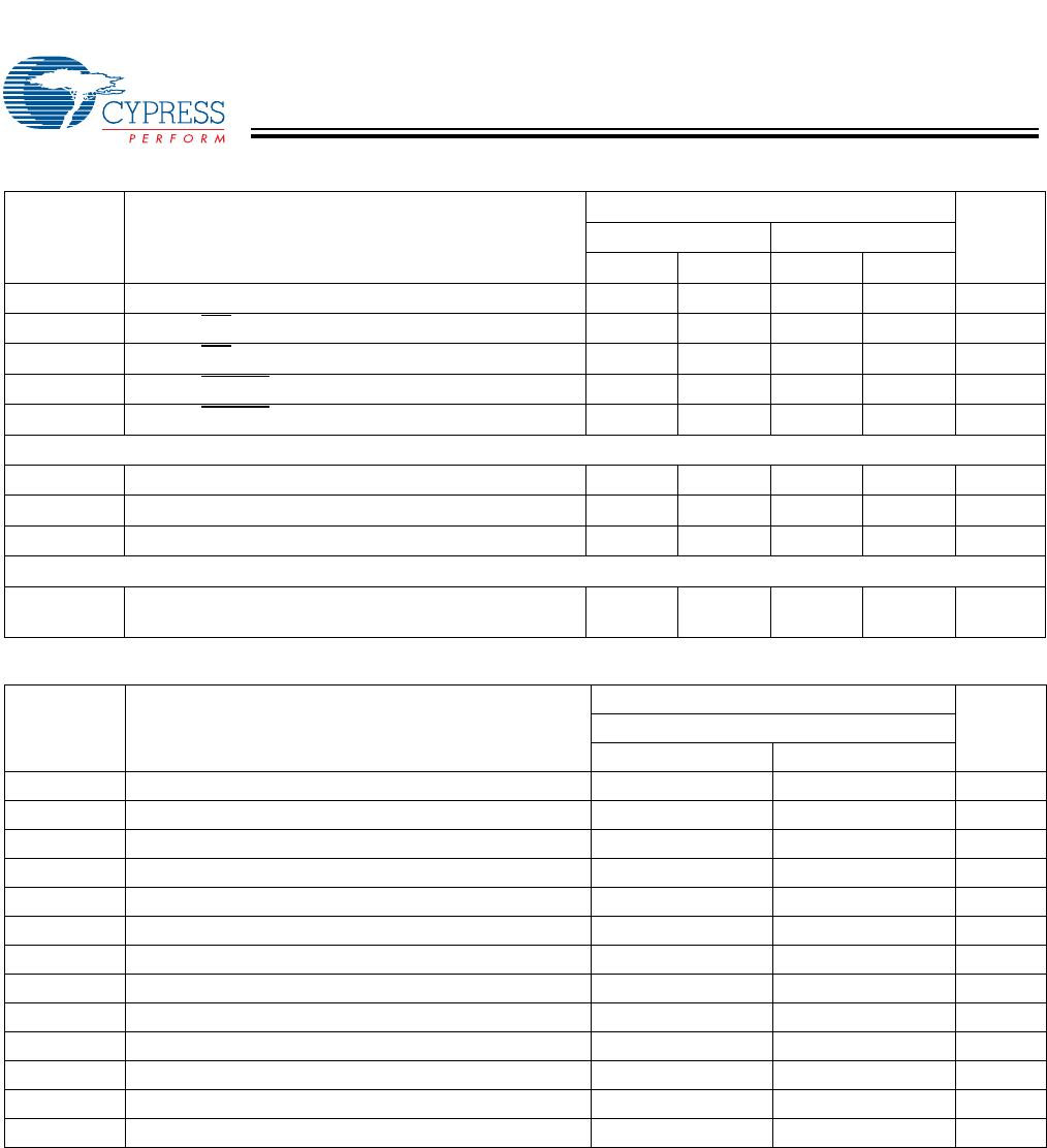
t
CKLZ
[9]
Clock HIGH to Output Low-Z 1 1 ns
t
SINT
Clock to INT Set Time 1 7.5 1 10 ns
t
RINT
Clock to INT Reset Time 1 7.5 1 10 ns
t
SCINT
Clock to CNTINT Set Time 1 7.5 1 10 ns
t
RCINT
Clock to CNTINT Reset Time 1 7.5 1 10 ns
Master Reset Timing
t
RS
Master Reset Pulse Width 7.5 10 ns
t
RSR
Master Reset Recovery Time 7.5 10 ns
t
ROF
Master Reset to Output Flags Reset Time 6.5 8 ns
Port to Port Delays
t
CCS
[6]
Clock to Clock Set-up Time (time required after a write
before you can read the same address location)
6.5 9 ns
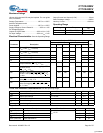
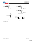
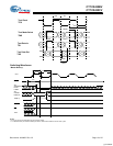
JTAG Timing and Switching Waveforms
Parameter Description
Quadport DSE Family
Unit
–133/–100
Min. Max.
f
JTAG
Maximum JTAG TAP Controller Frequency 10 MHz
t
TCYC
TCK Clock Cycle Time 100 ns
t
TH
TCK Clock High Time 40 ns
t
TL
TCK Clock Low Time 40 ns
t
TMSS
TMS Set-up to TCK Clock Rise 20 ns
t
TMSH
TMS Hold After TCK Clock Rise 20 ns
t
TDIS
TDI Set-up to TCK Clock Rise 20 ns
t
TDIH
TDI Hold after TCK Clock Rise 20 ns
t
TDOV
TCK Clock Low to TDO Valid 20 ns
t
TDOX
TCK Clock Low to TDO Invalid 0 ns
f
BIST
Maximum CLKBIST Frequency 50 MHz
t
BH
CLKBIST High Time 6 ns
t
BL
CLKBIST Low Time 6 ns
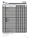
Switching Characteristics Over the Industrial Operating Range (continued)
[6]
Parameter Description
CY7C0430BV and CY7C0430CV
Unit
–133 –100
Min. Max. Min. Max.
[+] Feedback


