


CY7C0430BV
CY7C0430CV
Document #: 38-06027 Rev. *B Page 25 of 37
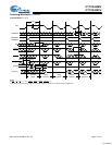
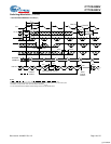
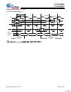
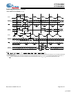
Counter-Mask Register
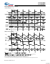
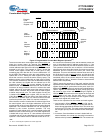
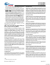
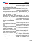
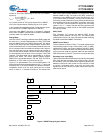
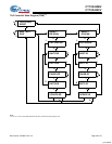
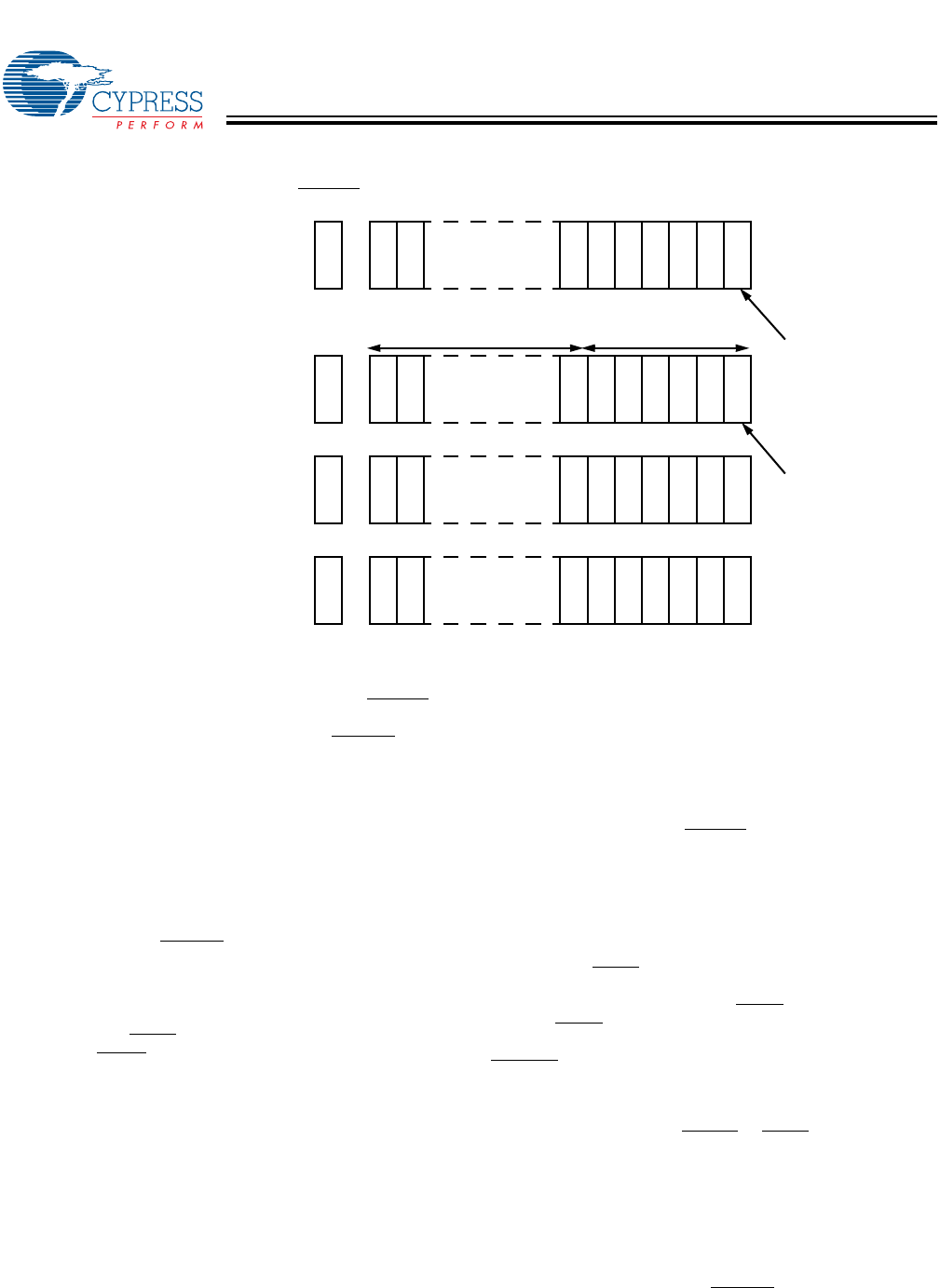
The burst counter has a mask register that controls when and
where the counter wraps. An interrupt flag (CNTINT
) is
asserted for one clock cycle when the unmasked portion of the
counter address wraps around from all ones (CNTINC must be
asserted) to all zeros. The example in Figure 2 shows the
counter mask register loaded with a mask value of 003F
unmasking the first 6 bits with bit “0” as the LSB and bit “15”
as the MSB. The maximum value the mask register can be
loaded with is FFFF. Setting the mask register to this value
allows the counter to access the entire memory space. The
address counter is then loaded with an initial value of XXX8.
The “blocked” addresses (in this case, the 6th address through
the 15th address) are loaded with an address but do not
increment once loaded. The counter address will start at
address XXX8. With CNTINC
asserted LOW, the counter will
increment its internal address value till it reaches the mask
register value of 3F and wraps around the memory block to
location XXX0. Therefore, the counter uses the mask-register
to define wrap-around point. The mask register of every port
is loaded when MKLD
(mask register load) for that port is
LOW. When MKRD
is LOW, the value of the mask register can
be read out on address lines in a manner similar to counter
read back operation (see Table 2 for required conditions).
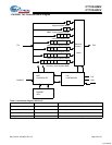
When the burst counter is loaded with an address higher than
the mask register value, the higher addresses will form the
masked portion of the counter address and are called blocked
addresses. The blocked addresses will not be changed or
affected by the counter increment operation. The only
exception is mask register bit 0. It can be masked to allow the
address counter to increment by two. If the mask register bit 0
is loaded with a logic value of “0,” then address counter bit 0
is masked and can not be changed during counter increment
operation. If the loaded value for address counter bit 0 is “0,”
the counter will increment by two and the address values are
even. If the loaded value for address counter bit 0 is “1,” the
counter will increment by two and the address values are odd.
This operations allows the user to achieve a 36-bit interface
using any two ports, where the counter of one port counts even
addresses and the counter of the other port counts odd
addresses. This even-odd address scheme stores one half of
the 36-bit word in even memory locations, and the other half
in odd memory locations. CNTINT
will be asserted when the
unmasked portion of the counter wraps to all zeros. Loading
mask register bit 0 with “1” allows the counter to increment the
address value sequentially.
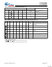
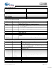
Table 2 groups the operations of the mask register with the
operations of the address counter. Address counter and mask
register signals are all synchronized to the port's clock CLK.
Master reset (MRST
) is the only asynchronous signal listed on
Table 2. Signals are listed based on their priority going from
left column to right column with MRST
being the highest. A
LOW on MRST
will reset both counter register to all zeros and
mask register to all ones. On the other hand, a LOW on
CNTRST
will only clear the address counter register to zeros
and the mask register will remain intact.
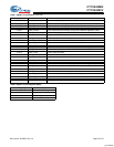
There are four operations for the counter and mask register:
1. Load operation: When CNTLD
or MKLD is LOW, the ad-
dress counter or the mask register is loaded with the ad-
dress value presented at the address lines. This value rang-
es from 0 to FFFF (64K). The mask register load operation
has a higher priority over the address counter load opera-
tion.
2. Increment: Once the address counter is loaded with an
external address, the counter can internally increment the
address value by asserting CNTINC
LOW. The counter can
2
15
2
14
2
6
2
1
2
5
2
2
2
4
2
3
2
0
2
15
2
14
2
6
2
1
2
5
2
2
2
4
2
3
2
0
2
15
2
14
2
6
2
1
2
5
2
2
2
4
2
3
2
0
2
15
2
14
2
6
2
1
2
5
2
2
2
4
2
3
2
0
H
H
H
L
11
0’s
1
0
1
0
101
00
X’s
1
X
0
X
0X0
11
X’s
1
X
1
X
1X1
00
X’s
0
X
0
X
0X0
Blocked Address Counter Address
Mask
Register
bit-0
Address
Counter
bit-0
CNTINT
Example:
Load
Counter-Mask
Register = 3F
Load
Address
Counter = 8
Max
Address
Register
Max + 1
Address
Register
Figure 2. Programmable Counter-Mask Register Operation
[51]
Note:
51.The “X” in this diagram represents the counter upper-bits.
[+] Feedback