CY7C64013C
CY7C64113C
Document #: 38-08001 Rev. *B Page 4 of 51
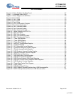
LIST OF FIGURES
Figure 6-1. Clock Oscillator On-Chip Circuit ..........................................................................................17
Figure 7-1. Watchdog Reset (WDR) ......................................................................................................18
Figure 9-1. Block Diagram of a GPIO Pin ..............................................................................................19
Figure 9-2. Port 0 Data ..........................................................................................................................19
Figure 9-3. Port 1 Data ..........................................................................................................................19
Figure 9-4. Port 2 Data ..........................................................................................................................19
Figure 9-5. Port 3 Data ..........................................................................................................................20
Figure 9-6. GPIO Configuration Register...............................................................................................20
Figure 9-7. Port 0 Interrupt Enable.........................................................................................................21
Figure 9-8. Port 1 Interrupt Enable.........................................................................................................21
Figure 9-9. Port 2 Interrupt Enable.........................................................................................................21
Figure 9-10. Port 3 Interrupt Enable.......................................................................................................21
Figure 10-1. Block Diagram of a DAC Pin..............................................................................................22
Figure 10-2. DAC Port Data...................................................................................................................22
Figure 10-3. DAC Sink Register.............................................................................................................22
Figure 10-4. DAC Port Interrupt Enable.................................................................................................23
Figure 10-5. DAC Port Interrupt Polarity ................................................................................................23
Figure 11-1. Timer LSB Register ...........................................................................................................23
Figure 11-2. Timer MSB Register ..........................................................................................................24
Figure 11-3. Timer Block Diagram .........................................................................................................24
Figure 12-1. HAPI/I2C Configuration Register.......................................................................................24
Figure 13-1. I
2
C Data Register...............................................................................................................25
Figure 13-2. I2C Status and Control Register........................................................................................25
Figure 15-1. Processor Status and Control Register .............................................................................28
Figure 16-1. Global Interrupt Enable Register .......................................................................................29
Figure 16-2. USB Endpoint Interrupt Enable Register ...........................................................................29
Figure 16-3. Interrupt Controller Function Diagram ...............................................................................30
Figure 16-4. GPIO Interrupt Structure....................................................................................................32
Figure 17-1. USB Status and Control Register ......................................................................................34
Figure 18-1. USB Device Address Registers.........................................................................................34
Figure 18-2. USB Device Endpoint Zero Mode Registers......................................................................35
Figure 18-3. USB Non-Control Device Endpoint Mode Registers..........................................................36
Figure 18-4. USB Endpoint Counter Registers ......................................................................................36
Figure 18-5. Token/Data Packet Flow Diagram.....................................................................................38
Figure 24-1. Clock Timing......................................................................................................................47
Figure 24-2. USB Data Signal Timing....................................................................................................47
Figure 24-3. HAPI Read by External Interface from USB Microcontroller..............................................47
Figure 24-4. HAPI Write by External Device to USB Microcontroller.....................................................48
[+] Feedback


