


INTRODUCTION
1
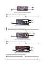
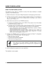
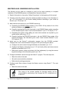
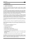
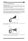
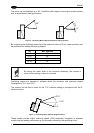
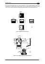
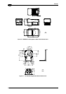
The following example represents the selection of an angle of +10° for the bottom line and an
angle of +20° for the top line (see figure below).
+17.5°
+37.5°
+27.5°
Figure 5 - Oscillating Mode
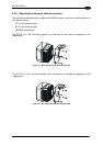
Refer to par. 2.2.1 for details about oscillating mirror mounting.
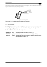
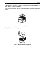
1.4 INDICATORS
T dec se
menus. The three keys present on the side of the display allow configuration menu
avigation (Figure CFigure , 1).
he three LED indicators have the following functions:
POWER ON
(red) Indicates the reader is turned on (Figure C, 4)
PHASE ON
(yellow) Indicates the presence sensor is turned on (Figure C, 3).
TX DATA
(green) Indicates the main serial interface is operating correctly during
data transmission (Figure C, 2).
he DS6300 oder ba provides an LCD display for system messages and configuration
n
T
5