


DS6300
2
Inputs
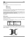
The inputs of the reader are on the 25-pin and 26-pin connector (Figure D, 1 and Figure E, 1)
of the DS6300.
These inputs are called EXT_TRIG/PS, IN2/ENC, IN3 and IN4.
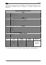
Pin Name Function
18 EXT_TRIG/PS A External trigger (polarity insensitive) for PS
19 EXT_TRIG/PS B External trigger (polarity insensitive) for PS
6 IN2/ENC A Input signal 2 (polarity insensitive) for Encoder
10 IN2/ENC B Input signal 2 (polarity insensitive) for Encoder
14 IN3A Input signal 3 (polarity insensitive)
15 IN4A Input signal 4 (polarity insensitive)
24 IN_REF Common reference of IN3 and IN4 (polarity insensitive)
IN2/ENC is normally used for the Encoder input. The maximum Encoder frequency is 2 KHz.
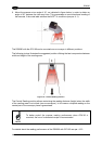
EXT_TRIG/PS is the main presence sensor. When active, this input tells the scanner to scan
for a code and that decoding can take place. The yellow LED (Figure C, 3) indicates the
EXT_TRIG/PS is active.
IN3 and IN4 can be used as the stop signal for the reading phase.
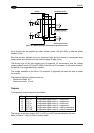
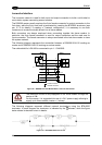
All inputs are optocoupled, polarity insensitive, and driven by a constant current generator;
the command signal is filtered through an anti-disturbance circuit which generates a delay
which can be set to 5 ms or 500 µs. In particular, EXT_TRIG/PS, IN3 and IN4 share the
same value which usually corresponds to 5 ms when using a photoelectric sensor, while
IN2/ENC has a different value which is set to 500 µs when this input is used for the Encoder.
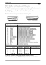
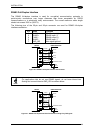
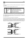
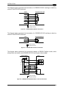
EXTERNAL TRIGGER/ENCODER
DS6300
+ 5V
A/B
Vext
B/A
V
~
~
+
-
Ground
Figure 24 – PNP Command Input Connection using External Power
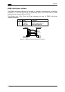
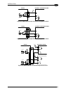
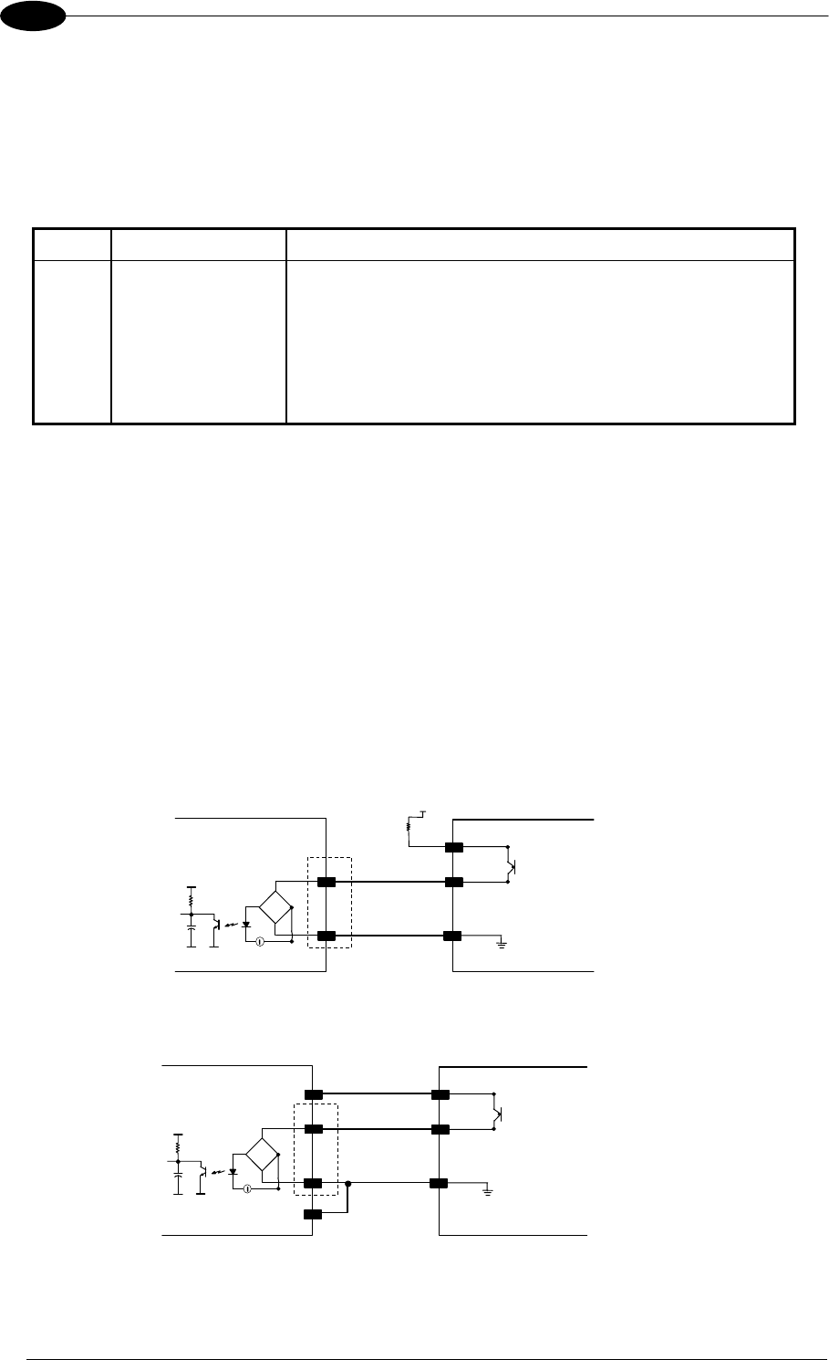
EXTERNAL TRIGGER/ENCODER
DS6300
+ 5V
A/B
B/A
GND
V
~
~
+
-
VS
Ground
Figure 25 - PNP Command Input Connection using Scanner Power
22