


DS6300
2
EXTERNAL DEVICE
DS6300
IN3A
Ground
V
+ 5V
~
~
+
-
EXTERNAL DEVICE
GND
V
IN4A
+ 5V
~
~
+
-
INREF
VS
Ground
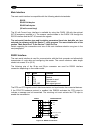
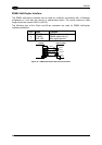
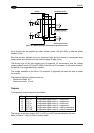
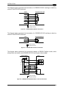
Figure 29 - IN3/IN4 NPN Input Command using Scanner Power
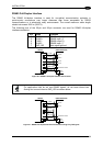
Input devices can be supplied by either scanner power (VS and GND) or external power
supplies (Vext).
Electrical isolation between the input command logic and the scanner is maintained when
powering the input devices from an external supply voltage (Vext).
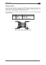
The driving logic of the input signals may be powered, for convenience, with the voltage
supply between pins 9 (VS) and 23 (GND) of the 26-pin I/O connector. In this case, however,
the device is no longer electrically isolated.
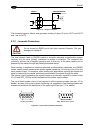
The voltage available on the 26-pin I/O connector, is physically the same as used to power
the scanner.
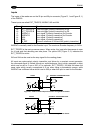
The electrical features of these inputs are:
Maximum voltage 30 V
Maximum current 10 mA
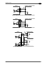
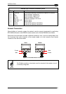
Outputs
Three general purpose outputs are available.
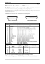
Pin Name Function
8 OUT 1+ Configurable digital output 1 – positive pin
22 OUT 1- Configurable digital output 1 – negative pin
11 OUT 2+ Configurable digital output 2 – positive pin
12 OUT 2- Configurable digital output 2 – negative pin
16 OUT 3A Configurable digital output 3 – polarity insensitive
17 OUT 3B Configurable digital output 3 – polarity insensitive
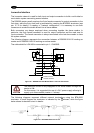
The function of the three outputs OUT1, OUT2 and OUT3 can be defined by the user.
Refer to Genius™ Help On-Line for further details.
24