


INSTALLATION
2
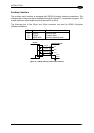
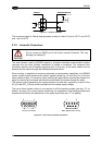
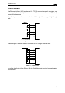
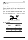
The diagram below represents the termination of a DS6300-XXX-010 working as master by
means of the BTK-6000 terminator.
Master
BTK-6000 Female Side
= male connecto
r
= female connector
8
6
7
9
6
9
3
2
8
7
3
2
LON A
LON B
VS
VS_I/O
GND
T
REF_I/O
Figure 36 – DS6300-XXX-010 Master Termination
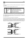
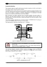
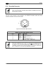
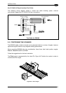
The diagram below represents the termination of a DS6300-XXX-010 working as slave by
means of the BTK-6000 terminator.
Slave BTK-6000 Male Side
8
7
8
7
LON A
LON B
T
= male connecto
r
= female connecto
r
Figure 37 – DS6300-XXX-010 Slave Termination
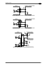
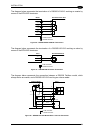
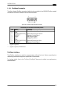
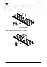
The diagram below represents the connection between a DS6300 Fieldbus model, which
always works as master, and a DS6300-XXX-010 working as a slave reader.
Fieldbus Master
8
Slave
3
7
5
4
3
5
4
VS_I/O
REF_I/O
9
1
2
8
7
9
1
2
LON A
LON B
VS
GND
AWG 16
AWG 16
T
= male connecto
r
= female connecto
r
CHASSIS
CHASSIS
Figure 38 – DS6300-XXX-010 Master/Slave Lonworks Connection
29