


INSTALLATION
2
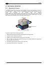
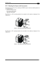
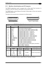
2.3.1 Main/Aux. Serial Interface and I/O Connector
The DS6500 master/slave model is equipped with a 25-pin male D-sub connector for
connection to the host computer, power supply and input/output signals.
The DS6500 fieldbus models (Ethernet, DeviceNet, Profibus) adopt a 26-pin male connector
instead of the 25-pin one.
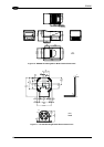
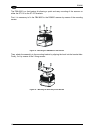
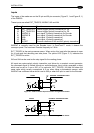
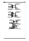
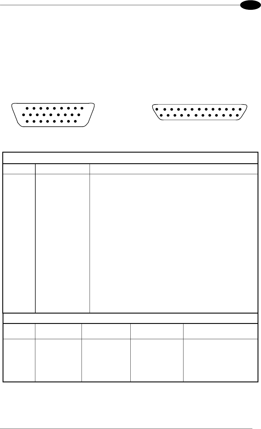
The details of the connector pins are indicated in the following table:
10
19
1
18
9
26
14
1
25
13
Figure 16 - 26-pin Connector Figure 17 - 25-pin Connector
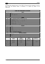
DS6500 25-pin/26-pin D-sub connector pinout
Pin Name Function
Chassis - internally connected to GND
1 CHASSIS
Cable shield connected to chassis
20 RXAUX Receive data of auxiliary RS232 (referred to GND)
21 TXAUX Transmit data of auxiliary RS232 (referred to GND)
8 OUT 1+ Configurable digital output 1 - positive pin
22 OUT 1- Configurable digital output 1 - negative pin
11 OUT 2+ Configurable digital output 2 - positive pin
12 OUT 2- Configurable digital output 2 - negative pin
16 OUT 3A Configurable digital output 3 - polarity insensitive
17 OUT 3B Configurable digital output 3 - polarity insensitive
18 EXT_TRIG/PS A External trigger (polarity insensitive) for PS
19 EXT_TRIG/PS B External trigger (polarity insensitive) for PS
6 IN 2/ENC A Input signal 2 (polarity insensitive) for Encoder
10 IN 2/ENC B Input signal 2 (polarity insensitive) for Encoder
14 IN 3A Input signal 3 (polarity insensitive)
15 IN 4A Input signal 4 (polarity insensitive)
24 IN_REF Common reference of IN3 and IN4 (polarity insensitive)
9,13 VS Supply voltage - positive pin
23,25,26* GND Supply voltage - negative pin
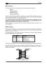
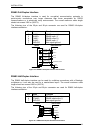
Main Interface Connector Pinout
Pin
RS232
RS485
Full Duplex
RS485
Half Duplex
20 mA C.L.
(INT-30 with C-BOX 100 only)
2 TX TX485 + RTX485 +
3 RX RX485 +
4 RTS TX485 - RTX485 - see INT-30 instructions
5 CTS RX485 -
7 GND_ISO GND_ISO GND_ISO
* Pin 26 is only available for fieldbus models (Ethernet, DeviceNet, Profibus).
15