


INSTALLATION
43
2
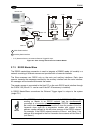
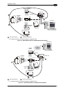
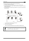
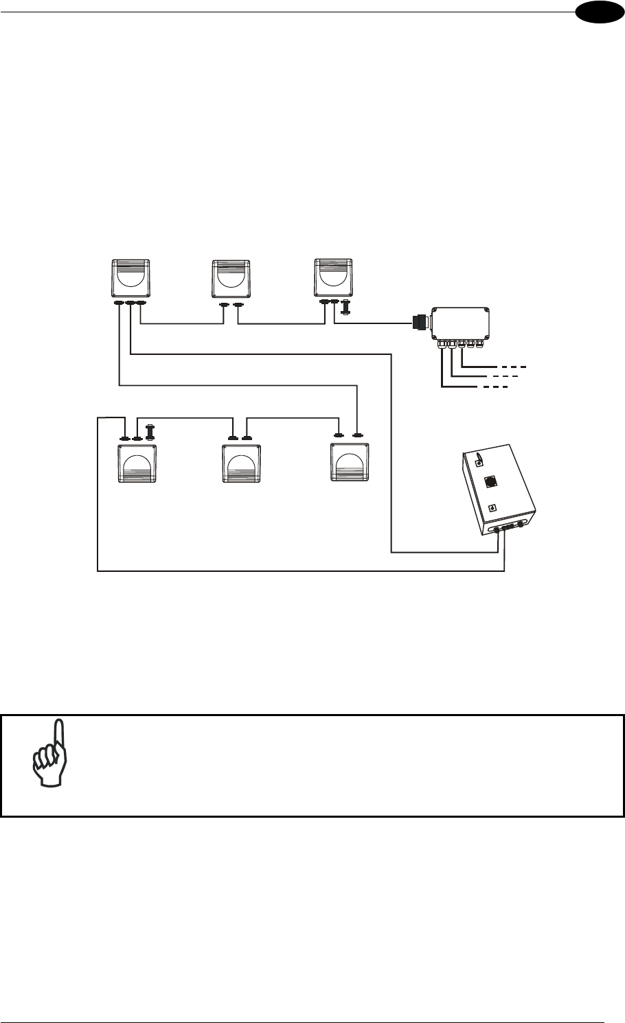
The following image shows a system consisting of six readers where:
• the system is powered by the PWR-240
• the master and all slaves are connected together through the CAB-610X cables
• the external signals (trigger, encoder, serial to host, etc.) are connected to the master
through the C-BOX 100
• one or more slaves are connected through CAB-63XX. The last slave must be terminated
with the BTK-6000
Master
Slave 2
Slave 1
C-BOX 100**
BTK-6000
CAB-610X
CAB-610X
CAB-600X
P.S.*
CAB-610X
Encoder***
Host
CAB-610X
CAB-610X
CAB-63XX
BTK-6000
Slave 3
Slave 5 Slave 4
PWR-240
CAB-63XX
* P.S. (Presence Sensor) connected to External Trigger/PS input.
** C-BOX 100 modified to accept scanner power.
*** Encoder connected to IN2/ENC input.
Figure 57 - Small Synchronized Network with more than 2 Readers and Single Power Unit
NOTE
If a single power source is used, it is not necessary to separate groups of
scanners with "no power" cables (CAB-611X).