INSTALLATION
2
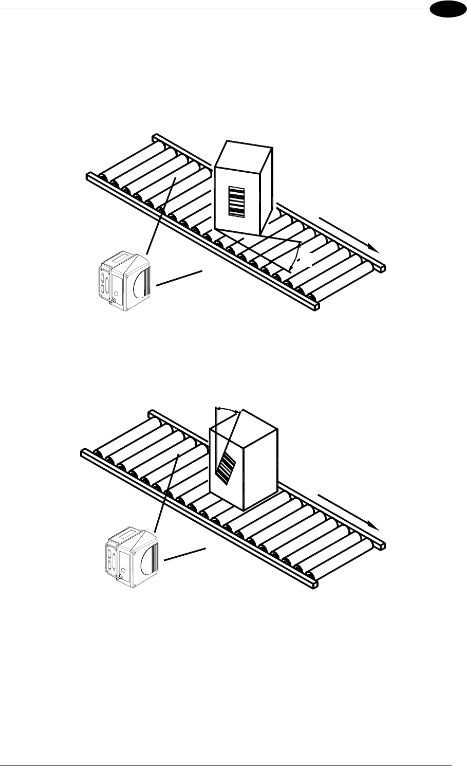
The Skew angle is represented by the value S in Figure 45. Position the reader to assure at
least 10° for the Skew angle. This avoids the direct reflection of the laser light emitted by the
scanner.
For oscillating mirror models, this angle refers to the most inclined or external laser line, so that
all other laser lines assure more than 10° Skew.
S
Figure 45 - "Skew" Angle
The Tilt angle is represented by the value T in Figure 46.
T
Figure 46 - "Tilt" Angle
33


