


INSTALLATION
2
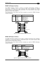
Lonworks Interface
The Lonworks network is used for both input and output connection to build a multi-sided or
omni-station system connecting several readers.
The DS6500 master usually employs the 9-pin female connector for output connection to the
first slave, while the 9-pin male one is terminated by inserting the BTK6000 terminator (see
par. 2.7.2 for details). If creating a T network configuration, it is necessary to use both
connectors to create the double branch line of slave readers.
Both connectors are always employed when connecting together the slave readers. In
particular, the 9-pin female connector is used for output connection and the male one for
input connection. The female connector is always terminated in the last slave reader to close
the system network.
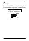
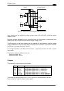
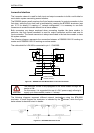
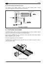
The following diagram represents the connection between a DS6500-XXX-010 working as
master and a DS6500-XXX-010 working as a slave reader.
The cable shield for LON A/B is connected to pin 1 - CHASSIS.
Master
8
Slave
3
7
5
4
3
5
4
VS_I/O
REF_I/O
9
1
2
8
7
9
1
2
LON A
LON B
VS
GND
AWG 16
AWG 16
= male connecto
r
= female connecto
r
CHASSIS
CHASSIS
Figure 32 – DS6500-XXX-010 Master/Slave Lonworks Connection
CAUTION
The maximum current to be propagated to the slave readers through the
master is 2 A.
For this reason, it is suggested the use of a 24 V power supply allowing to
supply up to three readers (master + 2 slaves).
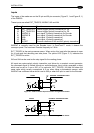
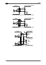
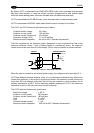
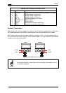
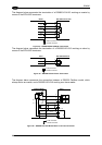
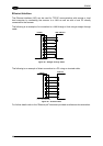
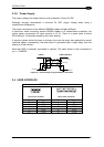
The following diagrams represent different network terminations using the BTK-6000
terminator. In each diagram the terminator is indicated by the
element, while the figure
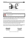
below shows its electrical circuit in details:
Figure 33 – BTK-6000 Electrical Circuit
25