


About Your System 13
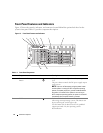
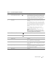
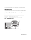
3 System identification button The identification buttons on the front and back panels
can be used to locate a particular system within a rack.
When one of these buttons is pushed, the LCD panel
on the front and the blue system status indicator on the
back blink until one of the buttons is pushed again.
4 LCD panel Provides system ID, status information, and system error
messages.
The LCD lights during normal system operation. Both
the system management software and the identification
buttons located on the front and back of the system can
cause the LCD to flash blue to identify a particular
system.
The LCD lights amber when the system needs
attention, and the LCD panel displays an error code
followed by descriptive text.
NOTE: If the system is connected to AC power and an
error has been detected, the LCD lights amber regardless
of whether the system has been powered on.
5 USB connectors (2) Connects USB 2.0-compliant devices to the system.
6 Video connector Connects a monitor to the system.
7 Diskette drive Optional.
8 Hard drives Eight hot-pluggable bays for 3.5-inch SAS or SATA hard
drives connected to a 1x8 SAS backplane.
9 Flex bay Optional flex bay drive bracket with 1x2 SAS backplane
for two additional 3.5-inch, hot-pluggable SAS or SATA
hard drives.
10 Tape backup unit Optional half-height SCSI tape backup unit (requires
optional SCSI controller). Optional full-height SCSI
tape backup unit also available.
11 Optical drive Optional.
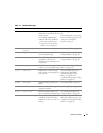
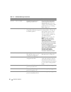
Table 1-2. Front-Panel Components (continued)
Item Component Icon Description