


Installing System Components 95
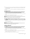
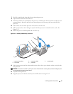
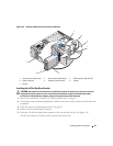
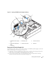
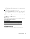
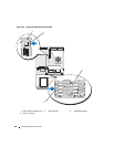
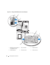
Figure 3-26. Installing and Removing the Flex Bay Drive Bracket
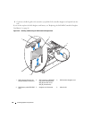
Installing the 1x2 Flex Bay Drive Bracket
CAUTION: Only trained service technicians are authorized to remove the system cover and access any of the
components inside the system. See your Product Information Guide for complete information about safety
precautions, working inside the computer, and protecting against electrostatic discharge.
1 Remove the front bezel, if attached. See
"Removing the Bezel" on page 50
.
2
Turn off the system and attached peripherals, and disconnect the system from the electrical outlet and
peripherals.
3 Open the system. See
"Opening the System" on page 53
.
4
Remove the flex bay filler panel, if present.
5 Insert the 1x2 flex bay bracket three-quarters of the way into the flex bay. See
Figure 3-26
.
The flex bay bracket is keyed for correct insertion into the flex bay.
1 peripheral bay release latch 2 SAS connector (SAS_B_IN) 3 SAS connector (SAS_B_OUT)
4 power connector 5 1x2 flex bay drive bracket 6 slot key
7 flex bay
2
7
5
1
3
4
6