


142 Jumpers and Connectors
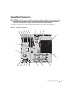
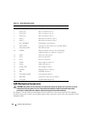
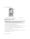
SAS Backplane Connectors
CAUTION: Only trained service technicians are authorized to remove the system cover and access any of the
components inside the system. See your Product Information Guide for complete information about safety
precautions, working inside the computer, and protecting against electrostatic discharge.
See Figure 6-3 for the location and description of the connectors on the back of the 1x8 SAS backplane
board. See Figure 6-4 for the location and description of the connectors on the back of the optional 1x2 SAS
backplane board.
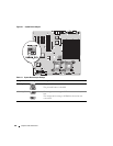
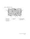
Table 6-2. System Board Connectors
Item Connector Description
1PCIE_X4_6 PCIe x4 connector (slot 6)
2PCIE_X4_5 PCIe x4 connector (slot 5)
3PCIE_X4_4 PCIe x4 connector (slot 4)
4 PCIE_X8_3 PCIe x8 connector (slot 3)
5 PCIX_2 PCI-X 64-bit connectors (slot 2)
6 PCIX_1 PCI-X 64-bit connectors (slot 1)
7 INT_STORAGE SAS daughter card connector
8 RAC_CONN Connector for the remote access controller (RAC)
9 RAC_MII_CONN RAC MII connector
10 DIMMn Memory module connector (12), numbered by
population order (see "Memory" on page 82)
11 FANn Fan power connector (6)
12 CPU1 Processor connector 1
13 CPU2 Processor connector 2
14 PWRn Power supply connector (2)
15 SATA_x SATA connectors (2)
16 PWR_CTRL Power supply connector
17 FLOPPY Floppy disk drive connector
18 IDE CD-ROM connector
19 CONTROL_PANEL Control panel connector
20 BATTERY Connector for the 3.0-V coin battery
21 TOE_KEY TCP/IP Offload Engine Key