


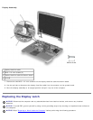
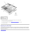

1 M2.5 x 6-mm screws (4)
2 M2.6 x 1.8-mm screws (4)
3 M2 x 4-mm screws (2)
4 M2.5 x 6-mm screws (2)
5. Remove the four M2.6 x 1.8-mm screws located inside the battery bay.
6. Remove the two M2.5 x 6-mm screws located near the service tag at the back edge of the computer.
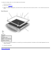
7. Turn the computer over and remove the two M2 x 4-mm screws located above the serial, docking, and video
connectors on the back panel.
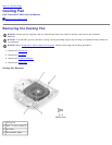
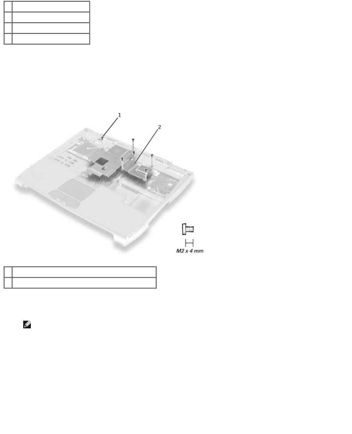
Critical Component Shield
1 M2 x 4-mm screws (6) (one screw may be captive)
2 critical component shield
8. Remove the six M2 x 4-mm screws (one of which may be captive) that secure the critical component shield to the
system board, and lift the shield away.
NOTE: At this point, the memory module under the critical component shield can be replaced.
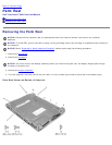
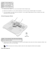
Palm Rest Removal