


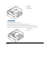

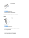

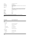

2. Rotate the power supply.
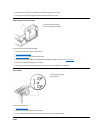
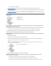
3. If necessary, remove a memory module:
a. Press out the securing clip at each end of the memory connector.
b. Grasp the module and pull up.
c. If the module is difficult to remove, gently ease the module back and forth to remove it from the connector.
4. To insert a module, press out the securing clip at each end of the memory connector.
5. Align the notches on the bottom of the module with the crossbars in the connector.
NOTICE: To avoid breaking the memory module, do not press near the middle of the module.
6. Insert the module straight down into the connector, making sure that it fits into the vertical guides at each end of the connector.
Press firmly on the ends of the module until it snaps into place.
If you insert the module correctly, the securing clips snap into the cutouts at each end of the module.
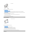
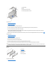
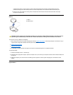
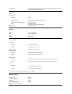
Heat Sink
The heat sink in your computer will be similar to one of those pictured in the preceding figure. To remove and replace the microprocessor and heat
sink:
1. Remove the computer cover.
2. Rotate the power supply.
3. Locate the microprocessor socket on the system board.
4. Release the metal clip that secures the heat sink and fan assembly to the microprocessor socket. Then remove the heat sink and fan
assembly from the microprocessor chip.
5. Disconnect the fan from the system board.
6. Remove and replace the microprocessor chip from the socket.
7. Unpack the heat sink and fan assembly included in your upgrade kit.
NOTICE: Ground yourself by touching an unpainted metal surface on the back of the computer.
8. Peel the release liner from the adhesive tape that is attached to the bottom of the heat sink and fan assembly.
9. Replace the heat sink and fan assembly.
NOTICE: When you install the heat sink and fan assembly, make sure that the heat sink is flat against the surface of the processor
while you are installing the clip. If the heat sink becomes tilted when you install the clip, excess heat can damage the processor.
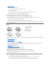
a. Place the heat sink and fan assembly on top of the microprocessor chip.
b. Orient the securing clip and hook the shorter side of the clip over the tab on the top edge of the microprocessor socket.
c. Press down on the top to the fan to snap the clip over the tab on the bottom edge of the microprocessor socket.
NOTE:Thesystemmemoryvaluereportedbytheoperatingsystemis1or2MBlessthanthememoryinstalledbecausethatmemory
is reserved for video functions.
1
Heatsinkandfanassembly
2
Heat-sink securing clip
3
Microprocessor
4
Microprocessor socket
5
Heat-sink securing tab