


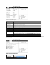

1. If possible, enter the system setup program and print the system setup screens by pressing the <Print Screen> key before you turn off the
computer because you will have to restore the configuration information after the system board is replaced.
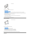
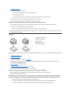
2. Remove the computer cover.
3. Remove the power supply.
4. Disconnect any cables connected to cards, and remove these cards.
5. Disconnect all internal cables from the system board.
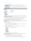
6. Remove the heat sink assembly.
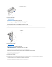
7. Remove the microprocessor.
8. Remove the memory modules.
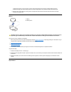
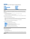
9. Push the system-board retaining clip until it disengages.
10. Slide the system board forward until is no longer held by the standoffs that secure the system board to the computer frame.
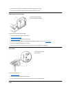
11. Carefully lift the system board out of the input/output (I/O) gasket and remove the board from the computer. The I/O gasket is on the back of
the computer where all of the input and output ports are located (see the system board).
When you install a replacement system board, angle the back of the board downward and carefully align the connectors on the back edge of the
board with the cutouts in the I/O gasket. When properly aligned, the board connectors slide into the I/O gasket as you lower the board into position
in the chassis and reseat it on the standoffs. Lock the board in place with the system-board retaining clip.
After you install the replacement system board, replace the microprocessor, the heat sink, the memory modules, and the cards that you removed
from the old system board.
Toconfigurethesystemafteryouinstallareplacementboard:
1. Install the jumper plug on pins 2 and 3 of configuration jumper J7A1 to select Maintenance mode operation.
2. Replace the computer cover, and start the computer.
The computer automatically starts the system setup program, adds the Maintenance option to the menu bar, and displays the Maintenance
screen.
3. Select Clear All Passwords, and press <Enter> twice.
4. Press <F10> to exit the system setup program and save any changes you made.
5. Turn off the computer, remove the computer cover, and replace the jumper plug on pins 1 and 2 of configuration jumper J7A1 to select
Normal mode operation.
6. Replace the cover, and start the computer.
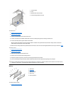
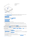
1
System-board retaining clip
2
System board
3
Standoffs
NOTE: You may need to slide the board toward the front of the computer to clear the hooked standoffs before you can lift the
board from the computer.