


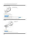


d. Connect the fan to the system board.
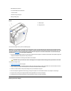
10. Replace the computer cover, and then reconnect your computer and peripherals to their electrical outlets and turn them on.
As the computer boots, it detects the presence of the new microprocessor and automatically changes the system configuration information in
the system setup program.
11. Enter the system setup program, and confirm that the Processor Type and Processor Speed options correctly identify the newly installed
microprocessor.
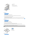
Microprocessor
NOTICE: Be careful not to bend any of the pins when you remove the microprocessor chip from its socket. Bending the pins can
permanently damage the microprocessor chip.
Your microprocessor socket is a zero insertion force (ZIF) socket with a lever-type handle that secures the chip in (or releases it from) the socket.
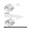
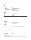
1. To remove the chip, pull the microprocessor-socket release lever out to unlock it and then straight up until the chip is released.
2. Remove the chip from the socket. Leave the release lever extended so that the socket is ready for the new microprocessor.
NOTICE: Ground yourself by touching an unpainted metal surface on the back of the computer.
NOTICE: Be careful not to bend any of the pins when you unpack the microprocessor. Bending the pins can permanently damage
the microprocessor.
3. Unpack the new microprocessor.
If any of the pins on the chip appear to be bent, obtain technical assistance.
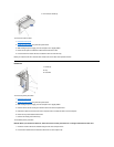
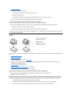
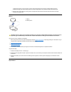
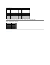
4. Align the pin-1 corner of the microprocessor chip with the pin-1 corner of the microprocessor socket, as shown in the following figure.
The pin-1 corner of the microprocessor is the beveled corner. The pin-1 corner of the socket, labeled "1," is the front-left corner of the
socket as you face the back of the computer.
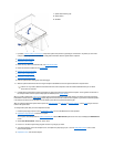
5. Install the microprocessor chip in the socket (as shown in the preceding figure).
NOTICE: You must position the microprocessor chip correctly in the socket to avoid permanent damage to the chip and the
computer when you turn on the system.
a. If the release lever on the microprocessor socket is not all the way out, move it to that position now.
b. With the pin-1 corners of the chip and socket aligned, align the pins on the chip with the holes in the socket.
c. Set the chip lightly in the socket and make sure that all pins are headed into the correct holes. Because your system uses a ZIF
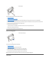
1
Microprocessor chip
2
Release lever
3
Microprocessor socket
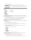
NOTE: You must identify the pin-1 corner to correctly position the chip.
1
Pin-1 corners of chip and socket aligned