


Back to Contents Page
System Board Assembly
Dell™Latitude™D531ServiceManual
Removing the System Board Assembly
Replacing the System Board Assembly
Removing the System Board Assembly
The system board's BIOS chip contains the Service Tag, which is also visible on a barcode label on the bottom of the computer. The replacement kit for the
system board includes media that provides a utility for transferring the Service Tag to the replacement system board.
1. Follow the instructions in Before Working Inside Your Computer.
2. Remove the media bay device (see Removing and Installing Media Bay Devices).
3. Remove the hard drive (see Removing the Hard Drive).
4. Remove any installed PC Cards (see Removing a PC Card or ExpressCard).
5. Remove the hinge cover (see Removing the Hinge Cover).
6. Remove the keyboard (see Removing the Keyboard).
7. Remove the display assembly (see Removing the Display Assembly).
8. Remove the palm rest (see Removing the Palm Rest).
9. Remove all memory modules (see Removing a Memory Module).
10. Remove the Mini-Card (see Removing the Mini-Card).
11. Remove the modem (see Removing the Modem).
12. Remove the processor thermal-cooling assembly (see Removing the Processor Thermal-Cooling Assembly).
13. Remove the processor (see Removing the Processor Module).
14. Remove the fan (see Removing the Fan).
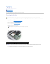
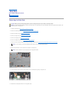
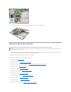
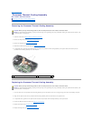
15. Remove the four 5-mm hex screws at the back of the computer.
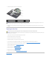
16. Remove the four M2.5 x 5-mm screws from the top of the system board.
CAUTION: Before you begin the following procedure, follow the safety instructions in the Product Information Guide.
NOTICE: To avoid electrostatic discharge, ground yourself by using a wrist grounding strap or by periodically touching an unpainted metal surface, such
as the back panel on the computer.