


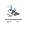
f. internal dual SD module
g. internal USB key (if installed)
h. PCIe card holder
i. cable retention bracket
j. if present, support bracket
NOTE: The support bracket is present on certain system configurations for protection during shipping and
can be discarded after removal.
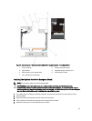
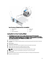
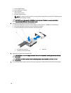
CAUTION: To avoid damaging the mini SAS cable and connector, follow the correct procedure when
removing the mini SAS cable from the system board.
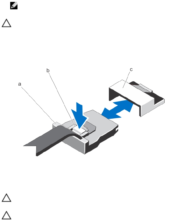
5. Disconnect the mini SAS cable from the system board:
a. Push the mini SAS cable connector to slide it further into the connector (J_SASX8) on the system board.
b. Press down and hold the metal tab on the mini SAS cable connector.
c. Pull the mini SAS cable out of the connector on the system board.
a. mini SAS cable connector b. metal tab
c. connector on the system board
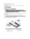
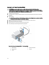
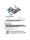
6. Disconnect all cables from the system board.
CAUTION: Take care not to damage the system identification button while removing the system board from
the chassis.
CAUTION: Do not lift the system board assembly by grasping a memory module, processor, or other
components.
7. Grasp the system-board holder, lift the blue release pin and slide the system board toward the front of the system.
120