


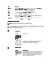

Item Indicator, Button, or
Connector
Icon Description
the front and the system status indicator on the back
flashes until one of the buttons is pressed again.
Press to toggle the system ID on and off.
If the system stops responding during POST, press and
hold the system ID button for more than five seconds to
enter BIOS progress mode.
To reset iDRAC (if not disabled in F2 iDRAC setup) press
and hold the button for more than 15 seconds.
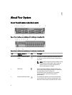
4 Video connector Allows you to connect a VGA display to the system.
5 LCD menu buttons Allows you to navigate the control panel LCD menu.
6 Information tag A slide-out label panel which allows you to record system
information such as Service Tag, NIC, MAC address and
so on as per your need.
7 LCD panel Displays system ID, status information, and system error
messages. The LCD lights blue during normal system
operation. The LCD lights amber when the system needs
attention, and the LCD panel displays an error code
followed by descriptive text.
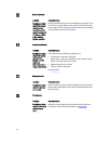
NOTE: If the system is connected to a power source
and an error is detected, the LCD lights amber
regardless of whether the system is turned on or off.
8 Optical drive (optional) One optional SATA DVD-ROM drive or DVD+/-RW drive.
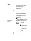
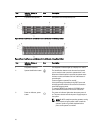
9 Hard drives
3.5 inch hard
drive systems
Up to eight 3.5 inch hot-
swappable drives.
2.5 inch hard
drive systems
Up to sixteen 2.5 inch hot-
swappable hard drives.
NOTE: In systems
supporting Dell PowerEdge
Express Flash devices (PCIe
SSDs), hard-drive slots 0
through 3 in hard-drive bay
2 support only PCIe SSDs.
Hard-drive bay 3 does not
support any hard drives and
is installed with a hard-drive
blank.
10 vFlash media card slot Allows you to insert a vFlash media card.
11 USB connectors (2) Allows you to connect USB devices to the system. The
ports are USB 2.0-compliant.
9